grandMA3 User Manual Publication
Connect LTC
|
grandMA3 User Manual » First Steps » Connect LTC
|
Version 2.0
|
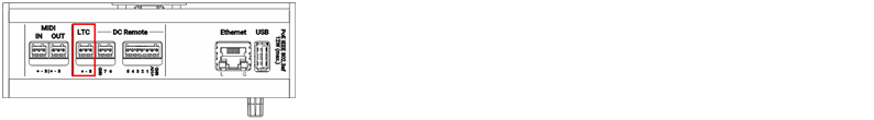
The LTC connector can be used for timecode input or for timecode output, e.g. to send the timecode signal to the sound engineer.
You can configure the direction of the LTC port in the Output Configuration.
To synchronize the console with an SMPTE timecode source, connect an SMPTE source to the LTC port.
|
|
Information: |
The supported time formats are: |
Sound and timecode signal levels
| Min. level | Max. level | Recom. level |
| -11 dBu 0.2 Veff |
+15 dBu 4.4 Veff |
0 dBu 0.8 Veff |
|
|
Information: |
| The signal strength should be a minimum of 200 millivolts. Pin 1: Ground Pin 2: - (minus) Pin 3: + (plus) |
- Connect the SMPTE source to the LTC connector on the rear panel of the console.
The SMPTE source is connected to the LTC connector.


To view the pinout of the DIN connector, refer to the topic Connector Pin Assignment.