grandMA3 User Manual Publication
Connect DC Remote In
|
grandMA3 User Manual » First Steps » Connect DC Remote In
|
Version 2.0
|
To use the DC Remote In with grandMA3 consoles, onPC command wings, and I/O Nodes connect a contact closure switch, for example, a light barrier or a push button.
For further information see the topics Remote keyword, Remote In and Out, and Output configuration.
|
|
Hint: |
| You can use up to 64 input channels within a session. |
|
|
Hint: |
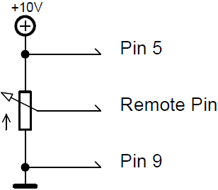
| It is possible to analogously move the Master Fader using a grandMA3 console or I/O Node connected with a potentiometer (0 to +10V DC). The onPC products can switch on and off, but do not fade. |
- Generate a switch or connect an external source that sends up to +10V DC to pin 1 for the console to react to analog input number 1.
- The recommended resistance is 5 kohms to 10 kohms.
- To use the DC Remote, feed a voltage signal (max. +10V DC into the corresponding input pin. For more information see the pinout image below.
To connect a switch:
- Take +10V DC voltage in pin 5 for the grandMA3 console or I/O Node
-or-
+5V DC voltage for grandMA3 onPC command wing and command wing XT - Take an external voltage source (+10V DC in grandMA3 consoles or I/O Nodes and +5V DC in grandMA3 onPC command wing and command wing XT), connect its ground to the common ground pin of the device.
Connect the +10V DC voltage source to one input pin 1-4 or 6-8 with a potential-free contact (switch, buzzer, motion detector, or any other switching device) in between.
Circuit examples:
- Potentiometer +10V DC in grandMA3 consoles or I/O Nodes
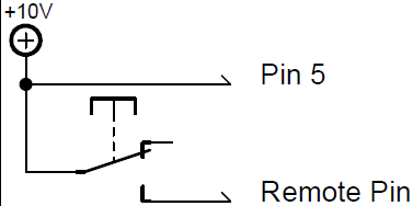
- Switch +10 DC in grandMA3 consoles or I/O Nodes
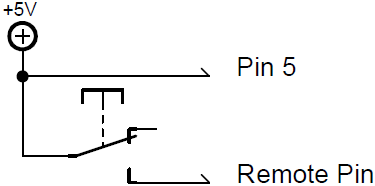
- Switch +5V DC in grandMA3 onPC command wing and command wing XT
|
|
Important: |
| Pin layout in grandMA3 consoles or I/O Nodes: The grandMA3 consoles or I/O Nodes have a 9-pin D-sub, enabling 7 remote inputs: Pin 1-4 = input channels 1, 2, 3, 4 Pin 5 = +10V DC grandMA3 consoles or I/O Nodes/+5V DC grandMA3 onPC command wing and command wing XT Pin 6-8 = input channels 5, 6, 7 Pin 9 = common ground |
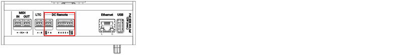
- Connect a D-sub plug to the DC Remote In connector on the rear panel.
DC Remote In control is connected.


To view the Pinout of the Sub-D connector, refer to the topic Connector Pin Assignment.