grandMA3 User Manual Publication
Installation
Installation
Hint:
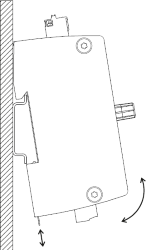
Install the grandMA3 xPort Node DIN-Rail on the rail following DIN EN 60715.
Install the grandMA3 xPort Node DIN-Rail on the rail following DIN EN 60715.
Important:
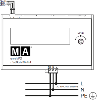
Install the grandMA3 xPort Node DIN-Rail horizontally so that the input terminal is located at the bottom and the DMX terminal on top.
Install the grandMA3 xPort Node DIN-Rail horizontally so that the input terminal is located at the bottom and the DMX terminal on top.
Warning:
In order for the device to dissipate heat, comply with a minimum distance of 30 mm (approx. 2 inches) above and beneath the grandMA3 xPort Node DIN-Rail.
In order for the device to dissipate heat, comply with a minimum distance of 30 mm (approx. 2 inches) above and beneath the grandMA3 xPort Node DIN-Rail.
- Install the grandMA3 xPort Node DIN-Rail onto the rail.
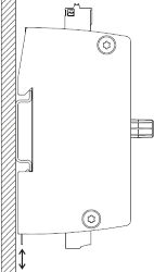
- Build the xPort Node DIN-Rail into the switchboard.
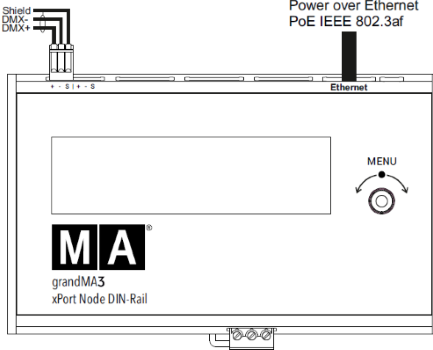
Connections
-or-
| Power | |
|---|---|
|
Connector |
MC 1.5/ 3-ST1-5.08 |
|
Rigid cables |
0.75 mm² - 1.5 mm² (18-16 AWG) |
|
Flexible cables |
0.75 mm² - 1.5 mm² (18-16 AWG) |
|
Wire stripping length |
7 mm |
|
Tightening torque |
0.22 Nm - 0.25 Nm |
| DMX | |
|---|---|
|
Connector |
FK-MC 0.5/ 3-ST-2.5 |
|
Rigid cables |
0.14 mm² - 0.5 mm² (26-20 AWG) |
|
Flexible cables |
0.14 mm² - 0.5 mm² (26-20 AWG) |
|
Wire stripping length |
8 mm |