Position Fixtures in the 3D Space
|
grandMA3 User Manual » Patch and Fixture Setup » Position Fixtures in the 3D Space
|
Version 2.1
|
The 3D Window shows a 3D visualization of the fixtures and objects in a 3D space.
The fixtures need to be positioned in the 3D space for this to truly be a powerful tool. The virtual fixtures should be positioned and rotated to match the real-world fixtures.
There are three primary ways to change the fixture position: Using the patch, using the 3D Viewer, or position calibration.
Position Fixtures Using the Patch
The best way to position the fixtures from the patch is from the Live Patch:
- Press Menu.
- Tap Live Patch.
- Make sure the menu is in Full column mode.
In the patch, there are rows for each fixture, and there are columns with position and rotation values:
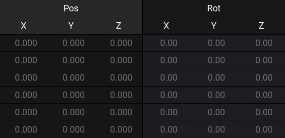
New fixtures are always added at the zero-point location and with zero rotation.
The zero points are 0.000 meters for all three position axes (X, Y, and Z) and 0.00° for all three rotation axes.
- X position is usually regarded as the Stage Left and Stage Right indication. A positive value is in the stage left direction.
- Y position is usually the Downstage and Upstage direction. A positive value would move the fixture more upstage.
- Z position is the height. A positive value would move the fixture above the stage.
- X rotation is rotating the fixture around the fixture's own X-axis. A positive value is rotating the top of the fixture towards downstage.
- Y rotation is rotating around the fixtures' own Y-axis. A positive value rotates the top towards stage left.
- Z rotation is rotating around the fixtures' own Z-axis. A positive value rotates the fixture counter-clockwise, as seen from the top.
The grandMA3 software currently only works with meters and degrees.
Do the following steps to edit the fixtures' position and rotation:
- Locate the rows for the fixtures that need to be positioned.
- Edit the needed fields.
- Type the new position.
The Show 3D Positions can be activated to show the 3D space with the fixtures. The fixtures represented by the selected rows are highlighted in yellow in the 3D space.
Position Fixtures Using the 3D Viewer
The 3D Viewer can be used to position and rotate the fixtures. It needs to be in Setup mode, which can be activated by tapping Setup in the title bar.
This mode changes the encoder toolbar into this:
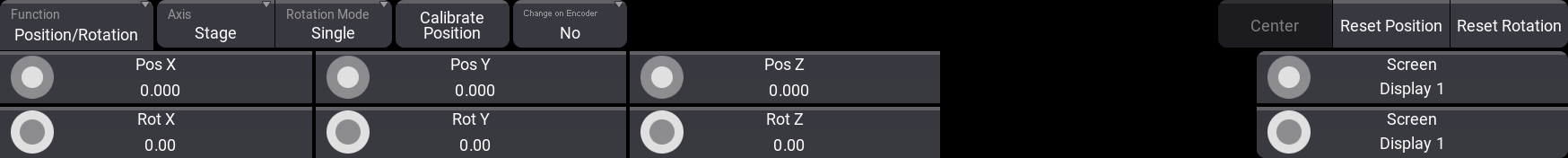
Different buttons in this toolbar change how the fixtures are affected by the encoders. Some standard functions do not change; others change depending on selected functions.
The general workflow is this:
- Select the fixtures that need to be moved.
- Change the settings in the toolbar to match the wanted action.
- Use the encoders to adjust the values.
The values on the encoders show the relevant values depending on the selected fixtures. Turning the encoders changes the values and thus the position or rotation of the selected fixtures.
These are the different standard buttons for position and rotation:
- Function:
This button toggles between two different modes: Position/Rotation and Arrangement. This changes the function of the encoders to either change the position and rotation of the selected fixtures or to different arrangement types. Read about the Arrangement tool below. - Axis:
The axis is used when a fixture is moved or rotated. The two options here are Stage and Object. This means that the selected fixtures can be positioned and rotated using their own axis (Object) or the stage or world axis (Stage). - Rotation Mode:
When multiple fixtures are selected, the rotation mode can be changed between Single or Group. This determines if rotation is done for each fixture or if the selection of fixtures is treated as a group and thus rotated as one object. - Calibrate Position:
This opens the Position Calibration menu. Read more about it below. - Change on EncoderEvent:
This determines when changes are distributed through the network to other stations. When it is set to Yes, then the new position is sent immediately. When it is No, then the new information is sent two seconds after the encoders stop turning. - Reset Position:
Tap this button to reset the fixture position to 0 in all positions. - Reset Rotation:
Tap this button to reset the rotation to 0 on all axes.
Position Arrangement Tool
The position arrangement tool consists of three different arrangement or layout types. It can be used to arrange the selected objects in a Line, Grid, or Circle.
The tool is accessed by changing the Function in the encoder toolbar to Arrangement. Each of the three layout types has its own encoder functions and their own buttons. There are some common arrangement buttons:
- Layout Type:
There are three types of arrangement: Line, Grid, and Circle. These different types change the available buttons in the encoder bar and the functions of the encoders. - Reset Encoder Values:
Resets the values on the encoder to the default values. - Apply on Change:
This controls whether arrangement changes are applied and distributed immediately (Yes) or only marked by a purple indicator of the would-be location (No). - Apply:
If Apply on Change is set to No, then this button needs to be tapped to confirm the new arrangement location.
When an arrangement is being adjusted, then there are purple fixtures in the 3D window with ID numbers to indicate where the fixtures would end up if the arrangement settings are applied.
Line
This is used to position the fixture on a single row.
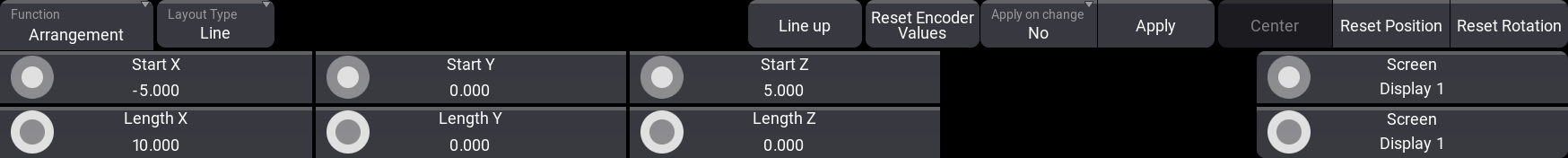
The encoders change to set a start and a length for all three axes. There is a special button called Line up. Tap this to align the base of the fixture to match the line.
Grid
The grid arrangement moves the fixtures into rows and columns. It is a 2D grid.
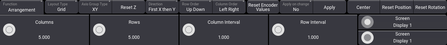
The encoders change to set the number of columns and rows and the interval spacing between the columns and rows. There are some special buttons:
- Axis Group Type:
This sets the orientation of the grid. It shows the two axes that are used as columns and rows. - Reset Z / Reset X / Reset Y:
This button resets the position on the third axis. The one not affected by the grid. - Direction:
This changes the direction of the grid. It changes the order of the two axes. - Row Order:
Tap this button to reverse the direction of the row. - Column Order:
Tap this button to reverse the direction of the row.
Circle
The circle arrangement tool is used to position fixtures in circles and spirals.
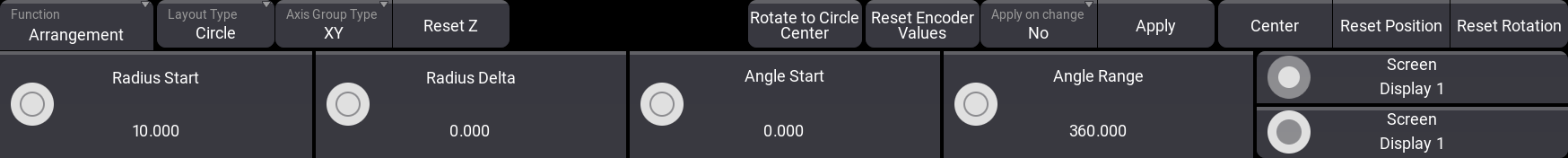
The encoders change to set the Radius Start size, Radius Delta (sets if the radius changes size), Angle Start, and Angle Range. Angle Start sets where the first fixture is on the circle. Angle Range is used when creating semi-circles (value below 360) or even multiple circles (value above 360).
There are some special buttons:
- Axis Group Type:
This sets the orientation of the circle. It shows the two axes that are used. - Reset Z / Reset X / Reset Y:
This button resets the position on the third axis. The one not affected by the circle. - Rotate to Circle Center:
This rotates the fixture bases to match the circle. Tapping this button several times rotates the fixtures, each time to a different rotation.
Position Fixtures Using Position Calibration
The fixture position calibration system calculates the fixture position based on the pan and tilt values needed to hit three or four known points in the real world. While using only points one, two, and three can be enough, the best result is achieved using all four points.
The four points do not need to be the same for all fixtures. Each fixture can have its own four points. The points are visible in the 3D window as a red, green, blue, and yellow octahedron when the window is in setup mode and the Position Calibration pop-up is open.
The pop-up is opened by tapping the Calibrate Position on the encoder bar - read above.
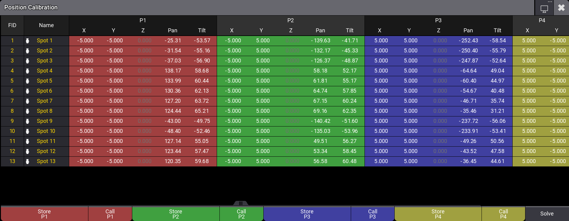
The pop-up shows the selected fixtures as rows and four colored sections of columns.
Each color section has X, Y, and Z values for the calibration point, and the Pan and Tilt values needed to hit the point.
At the bottom, there are buttons to store and recall the pan and tilt values for each point. There is also the Solve needed to start the position calculation.
To record the pan/tilt position that matches the calibration point, tap Store Px. Call Px can be used to recall a stored position to refine it.
|
|
Hint: |
| Four calibration points are recommended. Using three calibration points deteriorates the quality of the calibration. |
To calibrate fixtures, use this workflow:
- Open the Position Calibration pop-up.
- Select the fixtures to calibrate.
- Define the real-world coordinates of the calibration points (P1 - P4) in the position calibration pop-up for each fixture.
- Position each fixture using pan and tilt to each of the calibration points, and store these positions.
- Tap Solve.
- Close the pop-up.
Now the fixtures should move and rotate in the 3D window to match the real-world values.
Using the Command Line
Storing calibration points, calling calibration points, and solving the calibration can be done using the Action keyword.