|
grandMA3 User Manual » Phasers » Phaser Editor
|
Version 2.0
|
The Phaser Editor is a diverse tool for manipulating phasers.
It offers multiple means of visualizing running phasers as well as tools for dynamically creating and editing phasers. It can also be used as a simple trackpad to adjust the position attributes of fixtures.
Open a storable Phaser Editor window using the Add Window pop-up. Alternatively, open a temporary version of the Phaser Editor by tapping the Phaser button in the Encoder Bar.
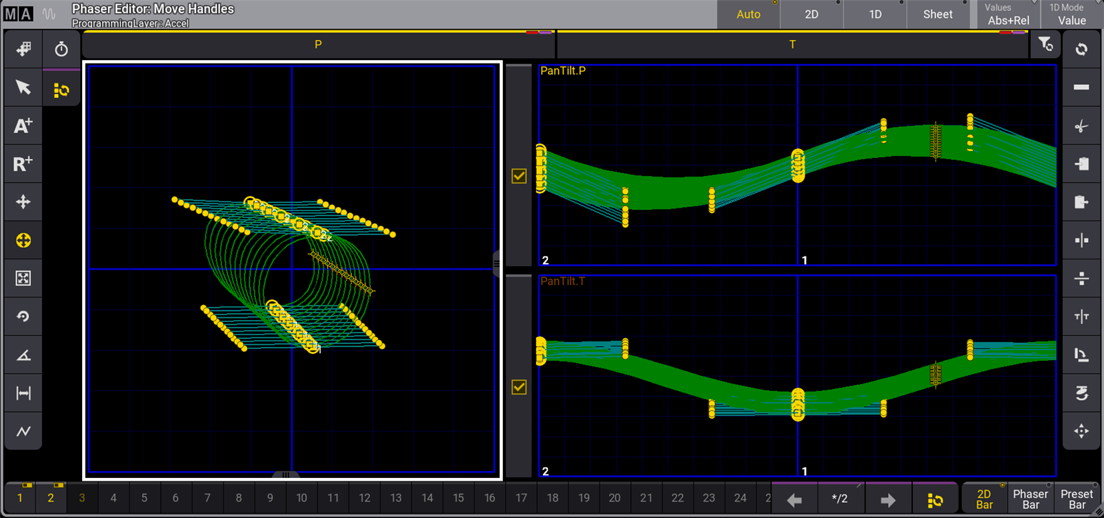
The image above shows the Phaser Editor in the Auto view mode. Choose between multiple available view modes using the radio buttons in the title bar or the drop-down button in the Window Settings pop-up. Read below for images and descriptions of the other available view modes.
The blue grid on the left represents the entire pan range (horizontally) and the entire tilt range (vertically). This is called the 2D layout.
The smaller blue grids on the right are 1D layouts. Each attribute with more than one step in the phaser is displayed in its own 1D layout. The bold, vertical, blue lines in the 1D layouts represent beats, based on the speed of the phaser. The example above shows pan and tilt attributes, each with two steps.
When fixtures are selected, they are visualized by small yellow cross-hairs. The beams can be represented in the 2D layout by toggling the Show Beams button in the Window Settings pop-up. When Show Beams is enabled, the intensity and color of each fixture are visualized as a larger circle behind the corresponding yellow cross-hair.
Adding points in the 2D layout adds steps to the programmer. The first point moves the fixtures to the specified position. Each subsequent point adds another step to the programmer.
When a step contains both an Absolute point (shown as a yellow or cyan-filled square) and a Relative point (shown as a hollow, yellow or cyan square), a thin red line connects the relative point and the related absolute point. The cyan-colored points show that the value is from a preset. Yellow-colored points are hard values from the programmer.
Selected points have a yellow circle around them.
A green line describes the path of the fixtures.
A row of buttons immediately below the title bar includes one button for each attribute included in the active phaser. These buttons function as a direct link to the At Filter. Phaser adjustments apply to any attributes with a yellow bar and yellow text. Attributes with a grey bar and grey text will ignore adjustments. Tap the button immediately to the right of the last attribute button in this bar to enable or disable all attributes in the bar.
|
|
Hint: |
| If any or all attributes in the bar are disabled, the first tap of the button to the right of the attributes enables all displayed attributes. If all displayed attributes are already enabled, tapping this button disables them all. |
The tool buttons on the left side are mouse or touch tools, and the tool buttons on the right are operational functions and shortcuts - read more below. The right side tool buttons might change depending on the selected tool on the left side.
Step Bar
The Step Bar appears across the bottom of the Phaser Editor. The Step Bar is a quick step selection tool. This element is optional in the Phaser Editor window, and it is enabled by default. Tap the Step Bar button in the Window Settings pop-up to show or hide the Step Bar. A storable window version of the Step Bar is also available in the More tab in the Add Windows pop-up.

Each step has a small square, which displays a status of empty, deselected, or selected.
Empty steps are steps that do not have any values. They have a dark background color.
Deselected steps have values in them, but they are not selected and are not affected by step-specific adjustments. Deselected steps have a light gray background color and an On/Off toggle icon in the upper-right corner.
Selected steps have values in them and are affected by step-specific adjustments. Selected steps have yellow text and a yellow On/Off toggle icon in the upper-right corner.
Tapping any of the steps toggles the selected status.
Additional controls appear on the right side of the Step Bar. These controls include left and right arrows used to change between single steps. An informative field appears between the arrows, showing which step is currently selected and the number of steps that contain values in the active phaser. If multiple steps are selected, the first selected step is shown with two dots after it (for example, 1../3). If all steps are selected, the first number is replaced with an asterisk (for example, */3).
Tap the ![]() button to the right of the right arrow in the Step Bar to select all steps. Tapping this selects all not-empty steps if only one step is currently selected. If more than one step is already selected, then only step 1 is selected. Tapping the button executes this command: Step Toggle Executor.
button to the right of the right arrow in the Step Bar to select all steps. Tapping this selects all not-empty steps if only one step is currently selected. If more than one step is already selected, then only step 1 is selected. Tapping the button executes this command: Step Toggle Executor.
The Step Bar in the Phaser Editor window includes three radio buttons. Tap one of these buttons to call up the desired encoder toolbar. The Preset Bar opens the standard attribute Encoder Toolbar with access to all layers and all attributes. See below for Images and descriptions of the 2D Bar and Phaser Bar.
|
|
Restriction: |
| The storable window version of the Step Bar does not include the encoder toolbar radio buttons. |
2D View Mode
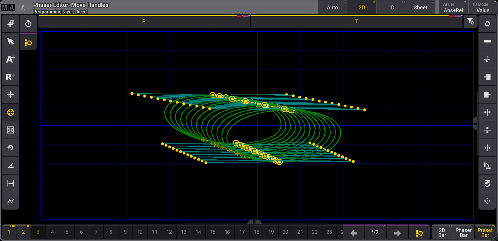
The 2D view mode removes other layout elements and expands the 2D layout to cover the main area of the window. This view mode is helpful when working with position phasers.
The Values button in the title bar allows or prevents the display and editing of absolute points or relative points. Tap to cycle through the available options or tap and swipe to open a list of available options. Options include:
- None - Displays and allows editing only of handles.
- Absolute - Displays and allows editing of absolute points and their handles.
- Relative - Displays and allows editing of relative points and their handles.
- Abs+Rel - Displays and allows editing of absolute and relative points, as well as their handles.
1D View Mode
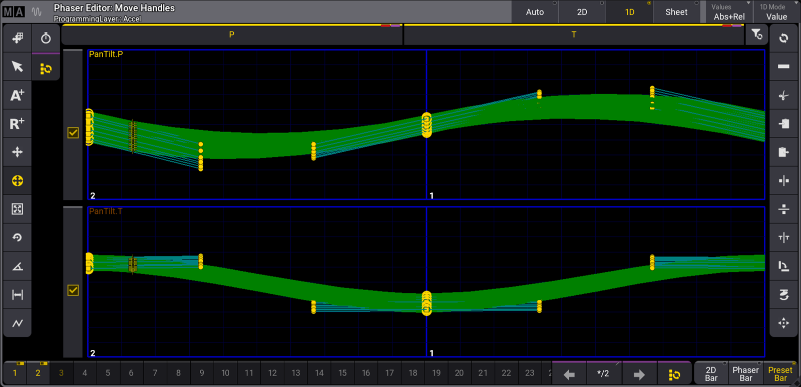
The 1D view mode removes other layout elements and expands the 1D layouts to cover the main area of the window. This view mode displays a layout for every attribute included in the active phaser.
To change the height of the attribute lines, tap the MA logo in the upper-left corner of the window, then tap LineHeight in the Window Settings menu, enter the desired height, and press Please.
The checkboxes to the left of the attribute lines represent the status of those attributes in the At Filter. These checkboxes relate directly to the attribute buttons across the top of the Phaser Editor. A yellow checkmark indicates that adjustments are allowed on the corresponding attribute. An empty, grey box indicates that adjustments are not allowed.
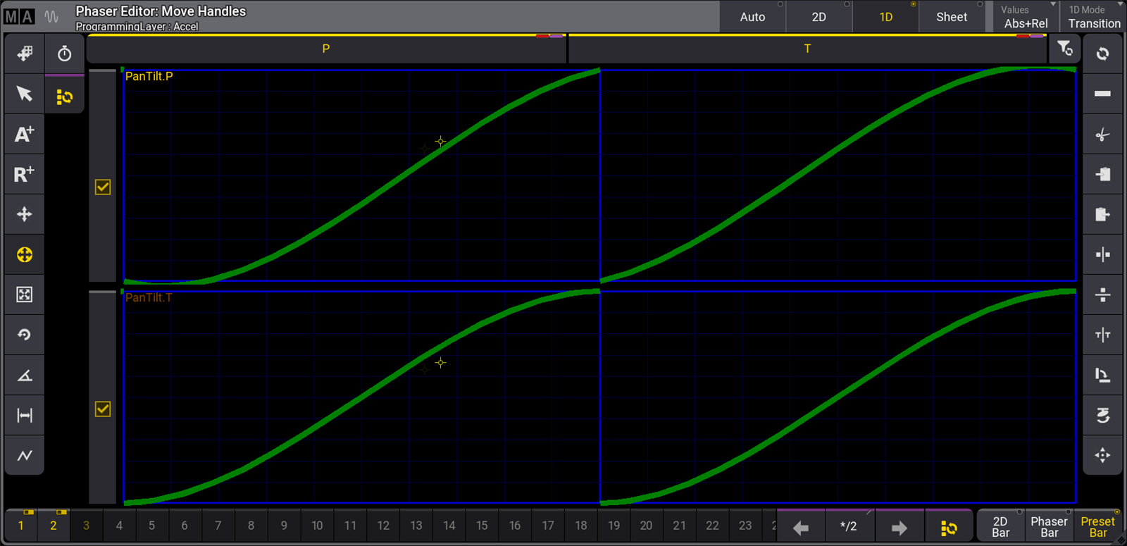
Tap the 1D Mode button at the right end of the title bar to toggle between the two available 1D drawing modes. These modes change the vertical scale of the 1D layouts.
- Value - In this mode, the vertical scale of each 1D layout equals the full range of values available for the displayed attribute.
- Transition - In this mode, the bottom of the vertical axis represents the beginning value for each step, and the top represents the ending value for the step.
Sheet View Mode
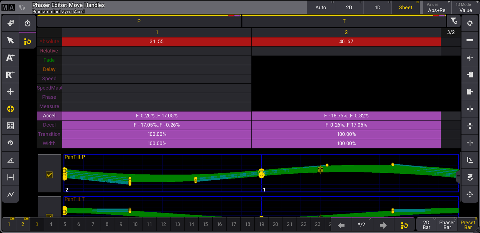
The step view mode displays phaser steps using a configurable spreadsheet format similar to the fixture sheet. Beneath all of the relevant spreadsheet data, this mode also includes 1D layouts for each attribute included in the phaser.
The default configuration of the sheet view mode arranges phaser steps as columns and layers as rows. Layers that affect all steps of the phaser appear only under step 1. Each cell in the sheet displays an overview of all values for the layer in that step. In cases where the cell includes multiple values or presets, the sheet displays the lowest and highest values in the cell separated by two dots.
The Display tab of the Window Settings pop-up includes some common Window Settings as well as some that are specific to the Phaser Editor.
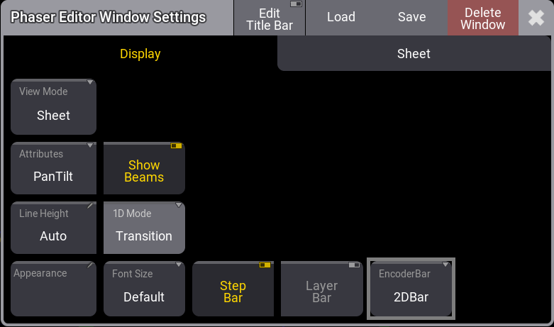
- Attributes - Defines which position attributes are used when creating a position phaser. Tap to toggle between PanTilt, XY, XZ, and YZ.
- Step Bar - Tap to show or hide the Step Bar.
- Layer Bar - Tap to show or hide the Layer Bar.
- EncoderBar - Defines which encoder bar is displayed in addition to the step bar. Tap to toggle between 2D Bar, Phaser Bar and Preset Bar.
The Sheet tab of the Window Settings pop-up includes some common Window Settings as well as some that are specific to the Sheet view mode of the Phaser Editor.
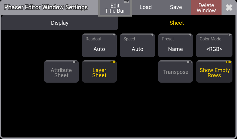
- Attribute Sheet - Tap to show or hide individual rows for each attribute included in the phaser. If Layer Sheet is enabled, each layer will include all of these individual layers.
- Layer Sheet - Tap either show all layers simultaneously or hide most layers, showing only the layer that is currently accessible on the attribute encoders.
- Show Empty Rows - Tap to show or hide empty rows.
Tools
The tool buttons on the left side are:

- 1 - Move Area:
Moves the entire blue pan/tilt square to show relative values that can be outside the position range. - 2 - Select:
Selects single steps or uses lasso selection for multiple steps. The selection can be filtered to Absolute and Relative steps by toggling the respective buttons in the title bar. - 3 - Add Absolute:
Adds a step using absolute value. The encoder bar follows the absolute layer. A filled rectangle represents absolute values. The Single Step Mode is automatically activated as long as you hold a finger or the mouse cursor in the editor while adding an absolute point. - 4 - Add Relative:
Adds a step using a relative value. The encoder bar follows the relative layer. An empty rectangle represents relative values. The Single Step Mode is automatically activated as long as you hold a finger or the mouse cursor in the editor while adding a relative point. - 5 - Move Point:
Moves selected steps. It is also possible to use the Align function. The Single Step Mode is automatically activated as long as you hold a finger or the mouse cursor in the editor while moving a single point. - 6 - Move Handles (The yellow highlight shows this is the current tool.):
Move handles of selected steps. It is also possible to use the Align function. Each point/step has two handles to influence acceleration and deceleration at the same time. Each handle has a cyan line connected to the point it controls. Move both handles of a point by touching the point and dragging in the desired direction. A handle can be moved individually by touching and moving the handle (small yellow circle). - 7 - Change Size:
Enlarges/reduces all selected steps evenly from the center point of the selection. It is also possible to use the Align function.
Pressing MA while changing the size enlarges/reduces all selected steps from the center point of the selection on the horizontal or vertical axis. - 8 - Change Rotation:
Rotates the selected steps around the center of the selection. It is also possible to use the Align function.
Pressing MA while changing the rotation, rotates the selected steps around the center of the selection in 5-degree increments. - 9 - Change Phase:
Opens an overlay with yellow dots symbolize the value of the phase for each fixture. Here the phase value can be shifted independently from the selected steps for the selected fixtures. The At filter can be used to move phases for individual attributes. It is also possible to use the Align and the Transition mode functions. If several attributes are displayed along with different phases, the selected feature groups are displayed in a brighter color. If the fixtures are allocated to grid positions, the values of the phases can be vertically or diagonally aligned. Selecting this also changes the functions on the right side to quick selections for alignment. This changes the tool buttons on the right side to give quick access to standard phase values and a Reset and Invert button. - 10 - Change Width:
The width can be changed with this tool. It changes the functions on the right side to shortcuts of different percentages. If all steps are selected and the Speed shortcut is tapped, then the movement speed is equalized between the steps. Default is that each step has the same width with no regard to the distance the fixtures are moving in the step. Equalizing the step width makes the fixture move at the same speed by adjusting the width. There is a Reset shortcut that resets the width. Default is a width of 100%. This means that each step has the same width with no regard to the travel distance of the fixtures in each step. - 11 - Select Form:
Selecting a form overwrites the values of the transition layer, accel layer and, decel layer to create the desired effect. Available forms are listed in the toolbar on the right side and include Rectangle, Sawtooth, Sine, Cosine, and Circle. - 12 - Change Speed:
Tap to display various speed tools in the right side toolbar. Available speed tools include functions which multiply or divide the current speed of the phaser by a given amount. Special speed options include:- Loop: Tap Loop to multiply the current phaser speed by the number of steps currently in the phaser.
- Fixture: Tap Fixture to divide the current phaser speed by the number of fixtures in the current selection.
- 13 - Select all Steps:
This is not a tool like the others. Tapping this toggles between all steps selected or the selection of single steps. It keeps the previously selected tool active.
|
|
Hint: |
| Some tools don’t require the user to precisely touch points in the 2D and 1D layouts to adjust them. Instead, make sure the desired steps are enabled in the Step Bar, and use the blue grid areas in the Phaser Editor as trackpads to make the desired adjustments. |
The standard operational functions on the right side are:

- 1 - Reset:
Reset spline of the selected steps. - 2 - Delete
Deletes the selected steps. - 3 - Cut Programmer:
Removes all programmer values in the currently selected fixtures and moves them to the clipboard. - 4 - Copy Programmer:
Copies all programmer values in the currently selected fixtures and moves them to the clipboard. - 5 - Paste Programmer:
Inserts all values from the clipboard to the currently selected fixtures in the programmer. - 6 - Mirror X:
Mirrors all selected points on the x-axis. - 7 - Mirror Y:
Mirrors all selected points on the y-axis. - 8 - Mirror Time:
Swaps the order of the steps. Select all steps first. This is the same as reversing the direction of the movement. - 9 - Swap XY:
Swaps the X and Y axes of the selected steps. - 10 - Flip:
Flips the position of the selected fixtures. - 11 - Reset Zoom:
Resets the area with the blue square.
Phaser Encoder Toolbar
Depending upon the type of encoder toolbar selected with the radio buttons in the bottom-right corner of the Phaser Editor, the encoder toolbar changes to display helpful tools, which are specific to the manipulation of Phaser data.
2D Bar
To enable the 2D Bar, tap 2D Bar in the bottom-right corner of the Phaser Editor.

This encoder toolbar includes the following encoder controls:
- MoveX: Turn the inner encoder to adjust the X position in the 2D Phaser grid of all steps currently enabled in the Step Bar.
- MoveY: Turn the inner encoder to adjust the Y position in the 2D Phaser grid of all steps currently enabled in the Step Bar.
- Size: Turn the inner encoder to adjust size of all steps currently enabled in the Step Bar. This allows encoder access to the Change Size tool mentioned above.
- Handle: Turn the outer encoder to adjust the handle length of all steps currently enabled in the Step Bar. This allows encoder access to the Move Handles tool mentioned above.
- Rotate: Turn the outer encoder to rotate all steps currently enabled in the Step Bar. This allows encoder access to the Change Rotation tool mentioned above.
- Aspect: Turn the outer encoder to adjust the aspect ratio of all steps currently enabled in the Step Bar. This tool simultaneously adjusts positions of points as well as length and direction of handles in order to create a wider or taller version of the current 2D form.
- Select Step: Turn the inner or outer encoder to select individual steps. Press the inner encoder or the outer encoder key to toggle between selecting all steps and a single step.
Phaser Bar
To enable the Phaser Bar, tap Phaser Bar in the bottom-right corner of the Phaser Editor.

This encoder toolbar allows for adjustment of Speed, Phase, Transition, Width, and Measure; based upon the current fixture and step selection, as well as the current status of the At Filter.