|
grandMA3 User Manual » Fixture Types » Build Fixture Types » Insert Geometries
|
Version 2.3
|
The geometry of a fixture is the physical description of parts of the device.
This example of a basic moving head consists of four components:
- Base
- Yoke
- Head
- Beam
Requirement:
- Tap Fixture Types, then select FixtureType 2.
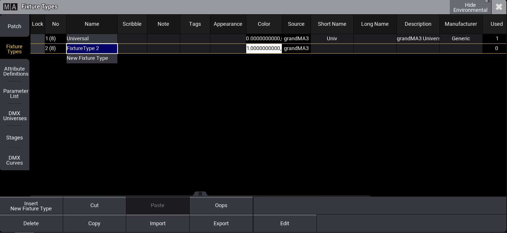
Select the fixture type you want to edit - To open the Fixture Type Editor, tap Edit. The window Edit
Fixture Type opens.
Fixture Type Editor - Tap Geometries.
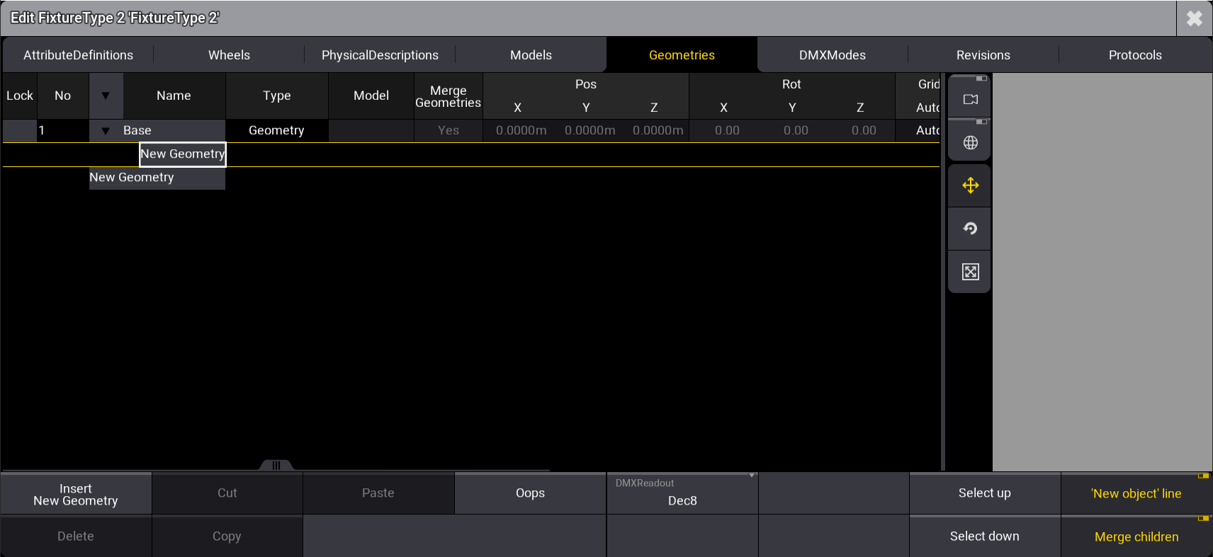
- Under the Name column, tap and hold Geometry and rename it Base.
- At the bottom right of the window, tap 'New object' line.
- Expand the Base tab by tapping
 , then select New Geometry.
The Geometries window opens.
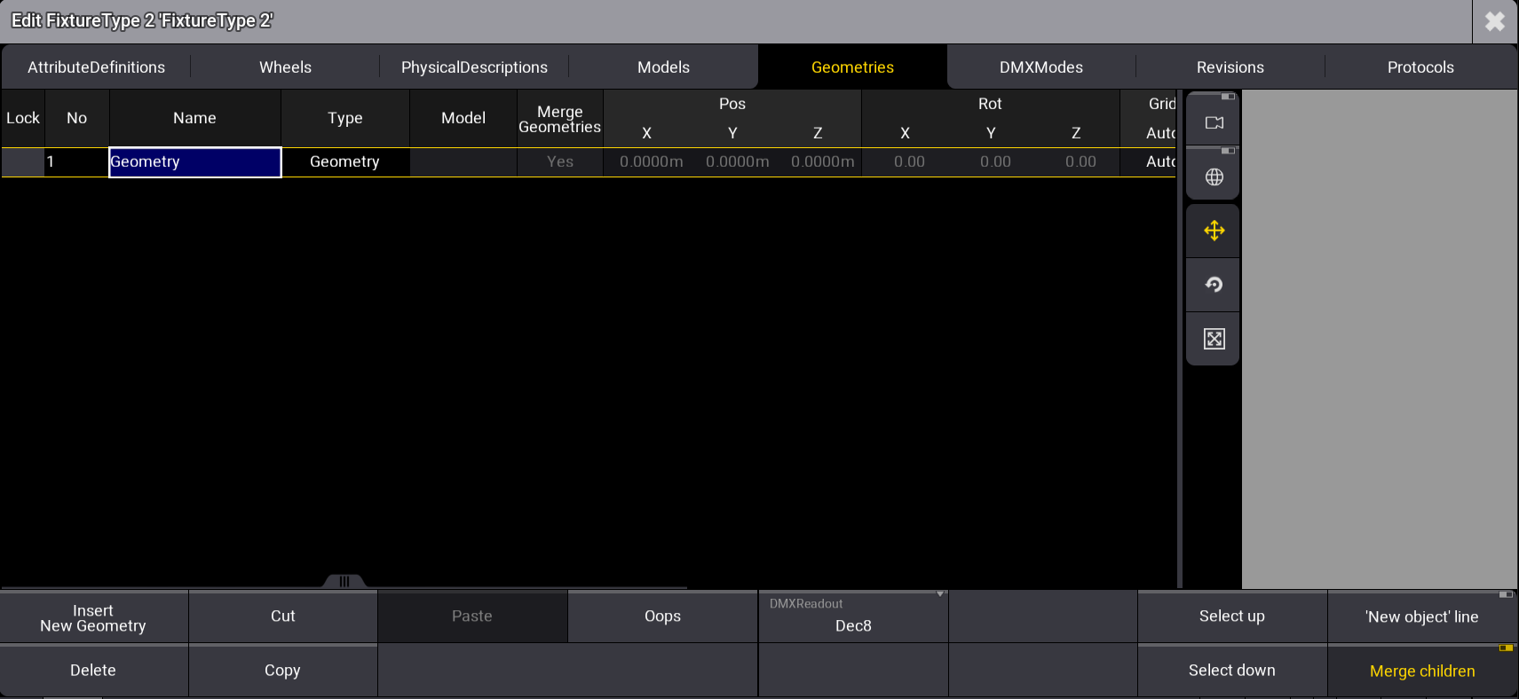
FixtureType Editor Geometries window with the Geometry Viewer on the right side
Insert new geometry
- Tap Insert New Geometry.
- Select Axis.
- Axis is now displayed in the column Type.
- In the column Name, rename Axis to Yoke.
- Press Edit and tap Axis, or press and hold Axis.
- The virtual keyboard opens.
- Enter Yoke.
- Expand the cell, Yoke.
- Yoke's child New Geometry opens.
- Repeat steps 6 to 8 and rename Axis to Head.
- Expand the cell Head.
- Head's child New Geometry opens.
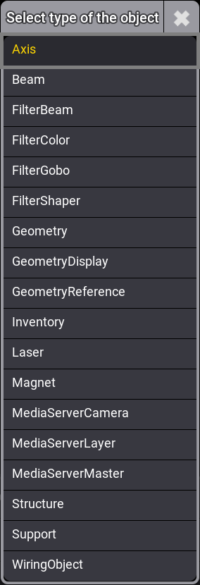
- Repeat steps 6 to 8, selecting Beam.
The pop-up Select type of the object opens.
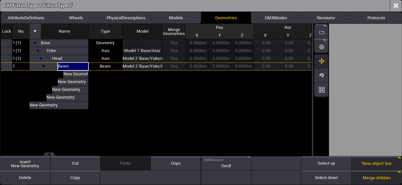
Geometries are inserted, as shown in the image below:
Sub-Fixtures Grid Position
The grid position of sub-fixtures can be modified manually under the Grid columns of the Geometry tab:
- Grid Auto: The positions are determined automatically by the position on the geometries (default value). When set to Manual, the user can define the grid positions independently using the following properties:
To better understand sub-fixture grid positioning, follow the steps below:
- Import the Martin Professional Mac Aura PXL fixture type and select it. For more information, see Import Fixture Types.
- Tap Edit at the bottom of the fixture type menu. The fixture type editor opens.
- Tap Geometries at the top of the window.
- Click the arrow on top of the window to expand all the lines.
- Select BeamLED 1.
The edit fixture type menu looks like this:
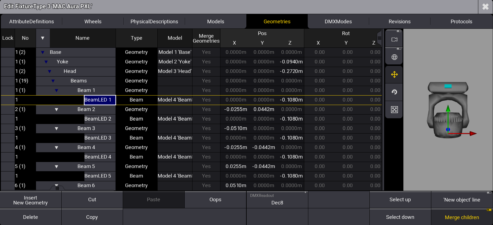
In the 3D area on the right side, colored indicators are displayed on the selected geometry. If the selected geometry is visible in the 3D model, the object itself is displayed in yellow. The values entered for Grid X, Grid Y, and Grid Z define the geometry position for all axes.
Grid settings per fixture are possible if, for example, the same fixture type is used for fixtures that are hung and on the floor. This is set in the patch menu:
Open the patch menu, press Menu, and tap Patch:
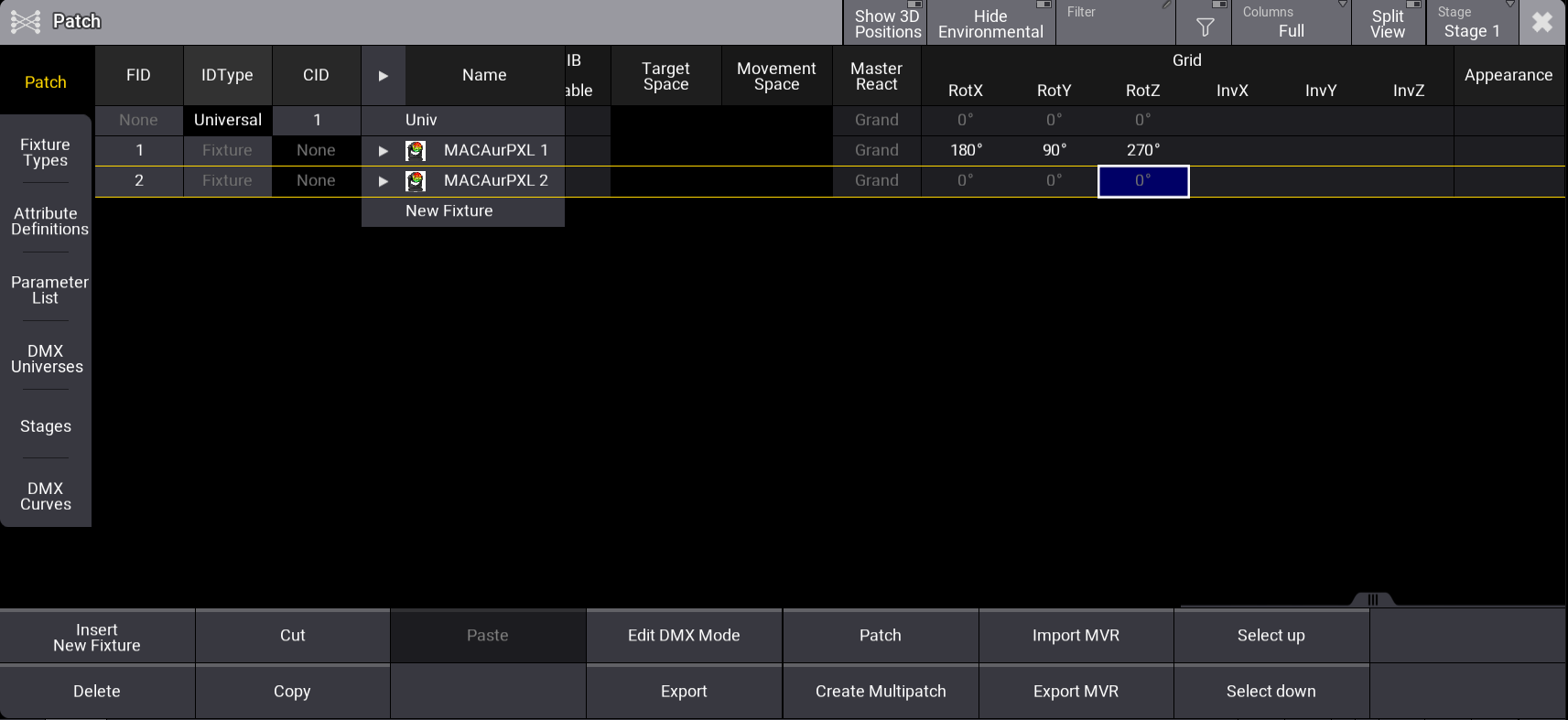
- Select a fixture.
- Set RotX, RotY, RotZ, InvX, InvY, and InvZ in the grid column.
After inserting the fixture type's geometries, the next step is to create models as a physical foundation for the fixture's different parts: Insert Models.