Sound Viewer
|
grandMA3 User Manual » Sound » Sound Viewer
|
Version 2.1
|
The grandMA3 system can receive a sound signal. This signal can be used in Phasers, and different Sound Channels can be used to give value to attributes or trigger cues.
The Sound Viewer displays an incoming audio signal as a raw waveform. This window also breaks down the strength of that signal into several bands of a few different widths. The Sound Viewer also displays calculations performed by the console to find steady beats within the signal.
Requirement:
Active sound input is required in order for the console to display useful information in the Sound Viewer. For information about connecting an audio input to a console, see the Connect Audio In topic. The grandMA3 onPC software uses any sound input hardware designated by the operating system.
The Add Window pop-up includes the Sound Viewer under the Tools tab. See the Add Windows topic for more information about the Add Window pop-up.
The right corner of the Sound Viewer title bar includes a View Mode button. Tap this button to cycle through available display mode options, or tap and swipe to open a pop-up menu containing all of the available display mode options for the Sound Viewer.
On the grandMA3 onPC, there is another button in the title bar called Audio In Device. This is a list of available sound devices on the computer that can be used as sound input devices. The used input can be selected here or in the onPC settings.
These settings define different settings specifically for the onPC. Learn more in the onPC Settings topic.
Wave View Mode
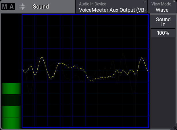
The left side of the window includes a simple VU meter, which is shown as a vertical bar.
The main area of the window shows the raw waveform of the incoming audio signal.
The right side of the window includes quick access to the Sound In master. Adjusting the Sound In master changes the volume of the input signal. This change is immediately visible in both the VU meter and the waveform. For more information about the Sound In master, see the Grand Masters topic.
Sound View Mode
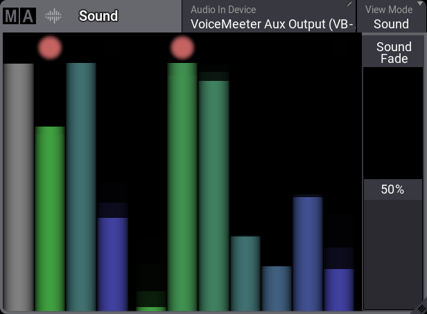
The Sound view mode of the Sound Viewer displays the incoming audio signal as a series of bars representing the volume of different bands of frequencies. When a given bar reaches a peak, a dot appears above the bar. This dot represents a possible sound trigger based on that frequency band.
The eleven bars shown in the window break down the frequencies of the audio signal in three different ways, displaying all three breakdowns simultaneously. The first bar represents the volume of the whole signal. The next three bars divide the signal into Bass, Mid, and High frequencies. And the remaining seven bars divide the frequencies equally into narrower bands.
These eleven bars relate directly to the first eleven Sound Channels and inversely to the remaining Sound Channels. Available Sound Channels include:
- All
- Bass
- Mid
- High
- Band1
- Band2
- Band3
- Band4
- Band5
- Band6
- Band7
- InvAll
- InvBass
- InvMid
- InvHigh
- InvBand1
- InvBand2
- InvBand3
- InvBand4
- InvBand5
- InvBand6
- InvBand7
Set the value of any parameter to follow one of the Sound Channels in the command line using the SoundChannel keyword or the Sound Codes tab of the Calculator.
The right side of the window includes quick access to the Sound Fade master. Adjusting the Sound Fade master changes the fall-off speed of all of the channels. While a lower number results in more accurate tracking of quickly changing dynamics, the response may appear undesirably erratic. A higher value results in a smoother response. For more information about the Sound Fade master, see the Grand Masters topic.
Beat View Mode
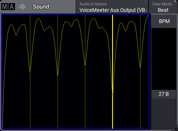
The Beat view mode of the Sound Viewer displays the incoming audio signal after some additional processing. This processing looks for repeating beats. The processed signal appears as a series of hills and valleys. Deeper valleys form where louder pulses in the incoming signal line up more consistently over time.
Dim, yellow, vertical lines appear in the valleys with the most consistent repeated pulses. These lines represent beat candidates, which the BPM speed master can follow.
A bold, yellow, vertical line appears when the BPM master locks onto a beat. The BPM master adjusts automatically to follow any changes detected in the incoming signal.
The right side of the window includes quick access to the BPM speed master fader. For more information about the BPM speed master, see the Speed Masters topic.