Selection Grid
|
grandMA3 User Manual » Operate Fixtures » Selection Grid
|
Version 2.4 |
Fixtures can have information about their position in a 3D selection grid.
Each fixture is represented by a box in the grid, which establishes the spatial relationships between fixtures for use with MAtricks, phasers, selection order, and effects.
The grid organizes the fixtures relative to each other, but not necessarily their positions in the
3D Viewer. Tap ![]() in the 3D Viewer toolbar to apply the current selection in 3D perspective to the selection grid. See 3D Viewer for more information.
in the 3D Viewer toolbar to apply the current selection in 3D perspective to the selection grid. See 3D Viewer for more information.
Tap a space on one of the screens to add the Selection Grid window. See Add Window.
Adjust the Selection Grid
The grid can be rotated by pressing the window with a single finger and moving the finger around the screen.
The grid can be zoomed using a pinch gesture with two fingers on a touchscreen or by scrolling the wheel on a mouse.
The grid can be moved by touching the screen with two fingers and dragging them across it. Alternatively, you can move it with the mouse by holding down the right mouse button while moving it.
Grid Cursor
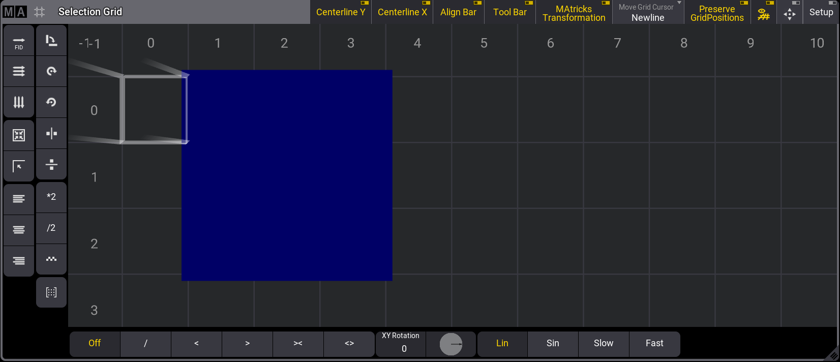
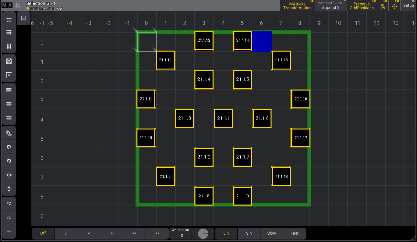
Fixtures are positioned based on the grid cursor's position, which is the blue cell.
The grid origin, 0/0/0, is marked with a white frame.
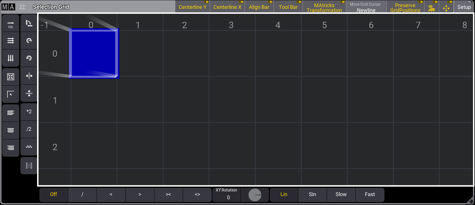
Selection Grid window
When a cell other than the origin 0/0/0 is selected, Preserve GridPositions in the title bar will be enabled. When it's disabled, all gaps and offsets to the origin will be removed.
The state of Preserve GridPosition can be recalled if it is disabled before storing the selection into an object.
When selecting fixtures, the Move Grid Cursor setting in the title bar will work as specified in the user profile. For more information, see User Settings.
These are the three modes for the Move Grid Cursor.
After a selection is made:
- None: The cursor will stay at its position when the selection is made.
- Append X: The Cursor will move to the next available X-axis cell on the grid.
- Newline: The cursor moves to X=0 on the following line.
Small icons in the upper left corner of the Selection button in the encoder bar display the used axes and the selected Move Grid Cursor setting:
 : x-axis
 : y-axis
 : z-axis
 : None
 : Append X
 : Newline
Tapping the Selection button in the encoder bar opens a temporary selection grid window.
Tap ![]() in the title bar to toggle the grid's visibility.
in the title bar to toggle the grid's visibility.
When tapping in the title bar, ![]() the window is reset to fit all the fixtures and the grid cursor in the selection grid window.
the window is reset to fit all the fixtures and the grid cursor in the selection grid window.
Tap the MA logo on the left side of the Selection Grid window's title bar to open the Selection Grid Window Settings.
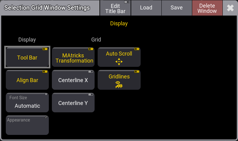
Selection Grid Window Settings
Buttons in the display column:
- Tool Bar: Shows or hides the toolbar in the Selection Grid window.
- Align Bar: Shows or hides the align bar in the Selection Grid window.
- Font Size: This selects the font size in the window. A swipe button opens a list of sizes from 10 to 32. There is also a Default property. The default is size 18.
- Appearances: Tapping this button opens a Select Appearance pop-up that lists all the defined appearances and allows you to create a new one. Selecting one will apply that appearance to the window.
- MAtricks Transformation: When applying MAtricks, this setting defines whether the transformation done by MAtricks is displayed in the Selection Grid window. The default value is Enabled.
- Centerline X: Displays a vertical red line across the Selection Grid window at the selection center.
- Centerline Y: Displays a horizontal red line across the Selection Grid window at the selection center.
- Auto Scroll: This toggle button activates the auto-scrolling function. When the sheet or grid is scrolled, the active object remains visible in the window.
- Gridlines: Shows or hides the grid lines.
To display or hide buttons from the Selection Grid window Title bar, tap Edit Title Bar in the Selection Grid Window Settings title bar:
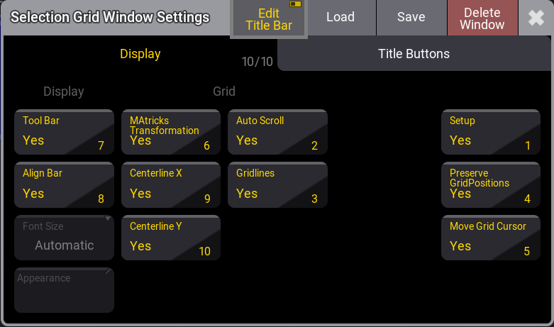
Selection Grid Window Settings - Edit Tool Bar active.
The grid cursor can be moved by tapping within the selection window, using the arrow keys on the keyboard, or entering the grid keyword. For more information, see Grid Keyword.
Pressing and holding MA + X3 | Grid will enter the grid keyword in the command line:
|
|
User name[Fixture]>Grid |
For example, moving the cursor to X position 1, Y position 2, and Z position 1, press the following keys:
MA + X3 | Grid 1 / 2 / 1 Please
If the Z-axis value is 1, it can be omitted.
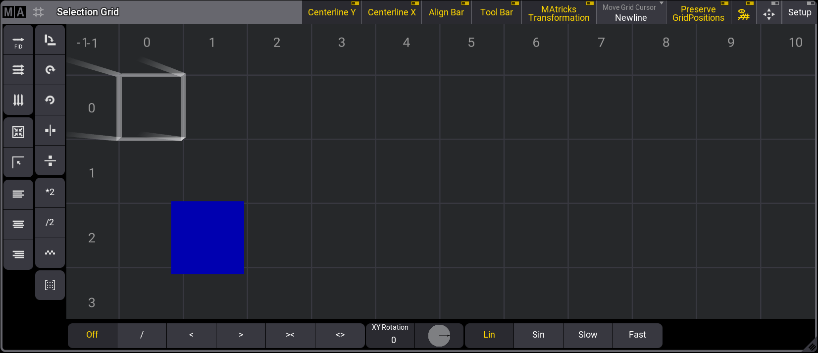
Selection Grid window with cursor moved to X position 1, Y position 2
Multiple Cells
The grid cursor can be more than one cell. For example, a square area of grid cells can be selected.
Use one of the following methods to select a range of cells:- Use the Thru keyword to specify the range of cells. For example, press the following keys: MA + X3 | Grid 1 Thru 3 / 2 Please
- Position the grid cursor at the starting point of the rectangle, press and hold the Shift key, then use the keyboard arrow keys to define the rectangle's size, or tap the desired endpoint of the rectangle.
- Position the grid cursor at the starting point of the rectangle, press and hold the MA key, then tap the desired endpoint of the rectangle.
Multiple cells are selected in the Selection Grid window.
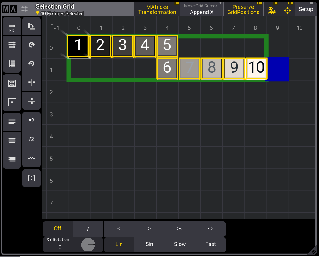
Selecting fixtures after defining the grid puts the fixtures in this area:
This will be the result if, for example, fixtures 1 thru 9 were selected and applied to the cell configuration above:
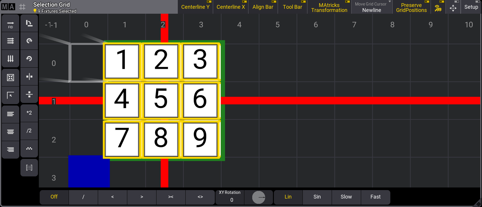
Selection Grid window with multiple cell selection
Fixtures can be added to the current selection:
- Move the cursor to where you want to add the following selection.
- Select some fixtures.
- The new selection is added to the grid.
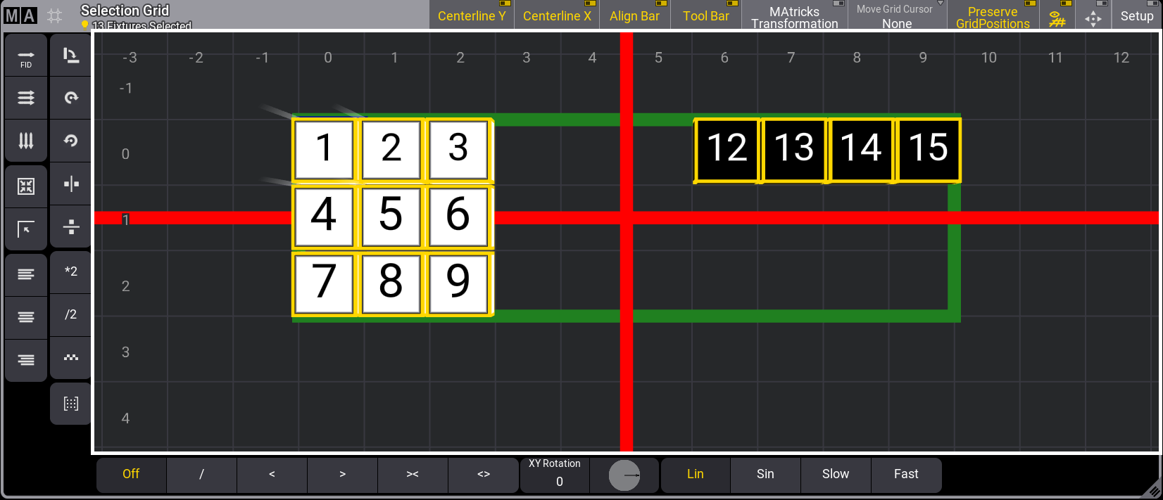
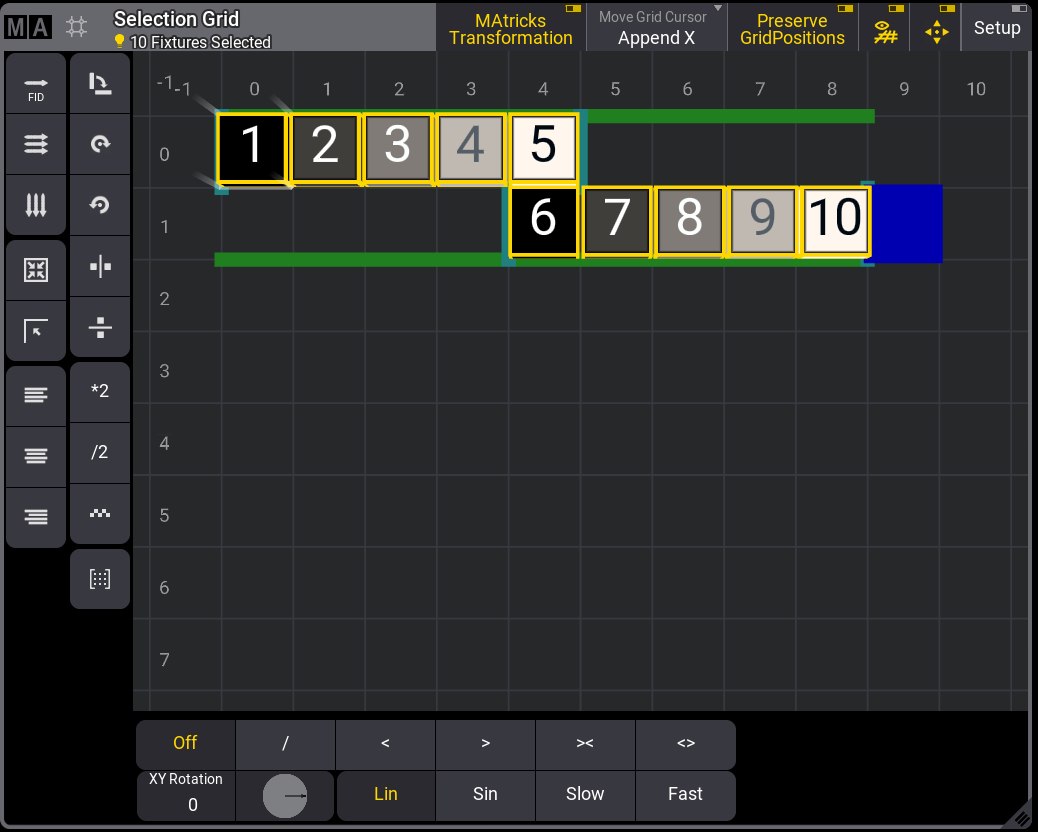
Selection Grid window with a new selection added
The horizontal and vertical red lines represent the center of the selection, and the green outline represents the overall selection.
Fixtures can be knocked out of the programmer by pressing Off and tapping a
fixture
in the selection grid.
Or a range of fixtures can be knocked out of the programmer by pressing Off Fixture 1 Thru 4 Please, for example.
Perspective and Planar
Perspective and planar modes can be used to position the fixtures in the selection grid based on the desired camera view:
These are the general syntax:
Grid "Perspective" Camera ["Camera_Name" or Camera_Number]
Grid "Planar" Camera ["Camera_Name" or Camera_Number]
|
|
Known Limitation: |
| At the moment, these two commands will not work if subfixtures are selected. |
Store the Grid
The grid information can be stored in groups, presets, or other objects when the fixtures are positioned.
Read more about storing groups in the Create Groups topic or generally about groups in the Groups topic.
You can read about storing presets in the Create Presets topic or, more generally, about presets in the Presets topic.
Read more about storing cues in the Store Cues topic or the cues and sequences section.
Group preferences are located in the Preferences and Timings menu.
To open the Preferences and Timings menu, press Menu, then tap Preferences and Timings.
Tap Groups on the left side at the bottom of the window.
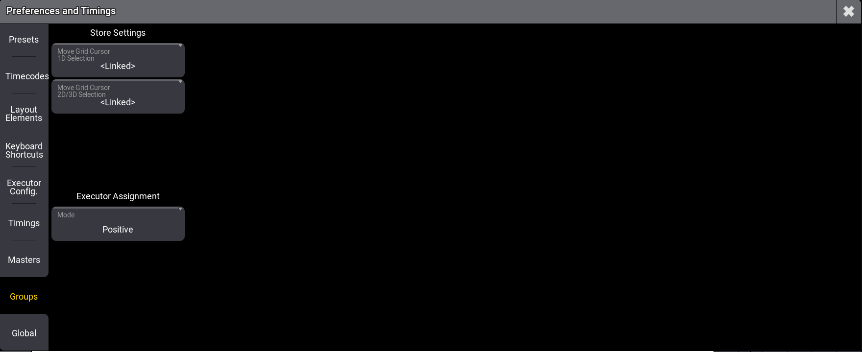
Preferences and Timing - Groups menu
- When Move Grid Cursor 1D Selection is enabled, Move Grid Cursor will be enabled in the stored group, given that the Selection Grid has a selection only in one dimension.
- Move Grid Cursor 2D/3D Selection will enable Move Grid Cursor in the stored group, given that the Selection Grid has a selection in at least two dimensions.
- MAtricks X, Y, and Z directions are relative to the entire range of selected fixtures.
When multi-instance fixtures are selected, pressing the Down key positions the subfixtures according to their arrangement within the main fixture. Press Up to return to the former selection. This works for all levels, and each level can have its own MAtricks.
The position defined by the geometries inside the fixture type will determine the grid position of the subfixtures. For more information, see Insert Geometries.
The image below is an example of subfixtures positions for the Mac Aura PXL:
Align Range Functionality
The Align Range functionality, Rx, Ry, and Rz in the MAtricks window, allows the user to define whether the values are to be aligned across the whole selection or individually per row/column. This can be defined separately per axis. When an Align Range is enabled, the frame around the selection in the Selection Grid window changes to a dark sea green color.
For example, to align ranges to be calculated per row rather than across the whole grid, enable Rx.
At 0 Thru 100 with Rx disabled:
For more information about align in general, see Align.