|
grandMA3 User Manual » Patch and Fixture Setup » Add Fixtures to the Show
|
Version 2.0
|
This is the process for adding new fixtures (or devices) to the show and the patch, using the GUI.
|
| Quick Steps in a new show: |
These are steps needed for adding the first fixtures to a new show - read below for details |
|
|
Quick Steps in a show with existing fixtures: |
These are steps needed to add more fixtures in an existing show - read below for details. |
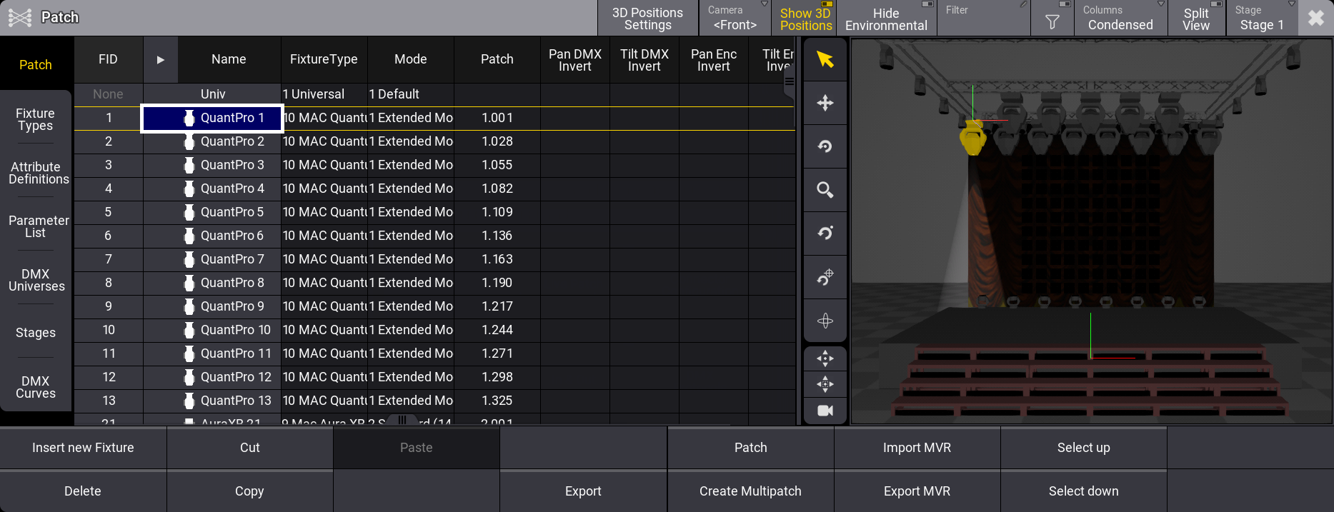
Everything about adding fixtures is done from the Patch menu.
Navigate to the Patch Menu
The Patch menu needs to be open to add fixtures.
- Press the Menu key.
- Tap the Patch button in the menu pop-up.
The patch menu is now open.
When the menu is opened the first time, a wizard helps to add the first fixtures to the show, and instead of the patch menu, there is a guide through the fixture selection and the Insert New Fixtures pop-up (see below).
Insert a Device in the Patch
Each fixture needs a row in the patch menu.
The fixtures belong to a "parent" stage object. The default parent is Stage 1. Several stages can be created - read more in the Stage topic.
The selected stage can be changed using the stage button in the title bar.
- Select the stage where the fixtures should be added using the button in the title bar.
- Tap the New Fixture area on the list if it needs to be added to the bottom, or tap an existing fixture to insert new fixtures above the selected fixture.
- Tap Insert new Fixture.
This opens the Insert New Fixture wizard pop-up on the Select DMX Mode to use part.
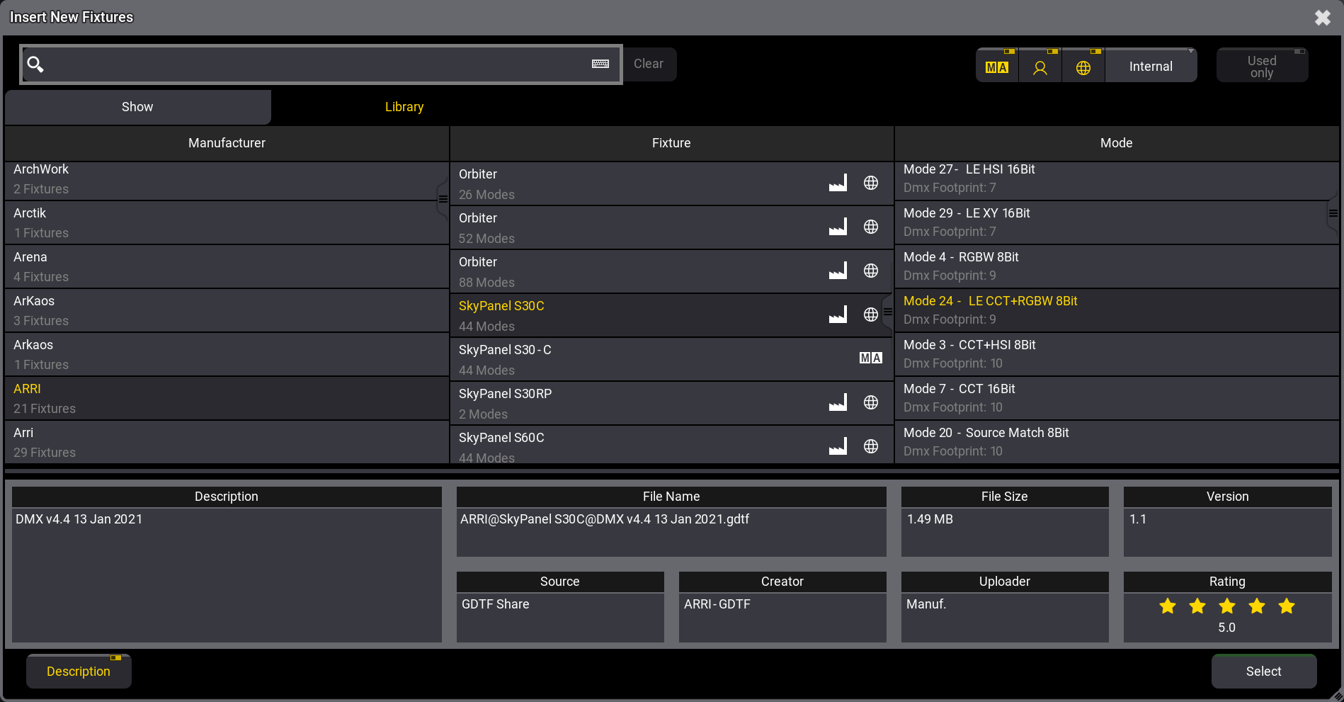
Below the search bar are two tabs: Show and Library. Show is the fixture types already imported into the show file. This list can be limited to only showing the patched fixture types. This can be done by activating the Used only button. The Library tab lists the different fixture types that can be used. With library selected, there are extra buttons available on the right side.
One button selects the drive. This makes it possible to select the internal drive, previously installed versions library, or an external USB drive. In the image above, it is the Internal button. The button is labeled to show the selected drive. Next to this button, there are small toggle buttons that select different sources.
The sources are MA ![]() (grandMA2 converted fixture files and grandMA3 fixture files), User
(grandMA2 converted fixture files and grandMA3 fixture files), User ![]() , and Shares
, and Shares ![]() (GDTF share and grandMA3 fixture share). The share button is only available when there is an active connection to a World Server (learn more in the World Server topic).
(GDTF share and grandMA3 fixture share). The share button is only available when there is an active connection to a World Server (learn more in the World Server topic).
|
|
Restriction: |
| grandMA2 fixture files cannot be loaded directly into the grandMA3. The grandMA2 converted source mentioned above is the grandMA2 library converted to match the grandMA3 structure. Fixture files are converted when a grandMA2 file is stored as a grandMA3 file. Learn more in the grandMA2 manual / Using the Backup Menu / Save as grandMA3. |
- Select the desired drive and activate the desired sources.
The fixture libraries are sorted by manufacturers in the left column. Selecting a manufacturer lists the fixtures from that manufacturer in the center column. Selecting a fixture lists the available modes in the right column.
At the bottom, a Description button can show an area with extra information about the selected fixture type file.
- If the list is long, filtering it by typing a word in the Search input might make sense. The search is across manufacturers, fixtures, and modes (If a fixture has multiple modes, it will show them all, but only fixtures that include the searched mode).
- Select the desired fixture and mode from the list and tap Select.
This reveals the Insert New Fixtures Wizard. This has a list of elements that needs information to add the fixtures to the patch. The wizard comes in two different modes, depending on the Columns mode of the patch. This mode can be toggled in the Columns button in the title bar. When the mode is Full then, there are more elements (ID Type, CID, Layer, and Class). This is the full version of the pop-up:
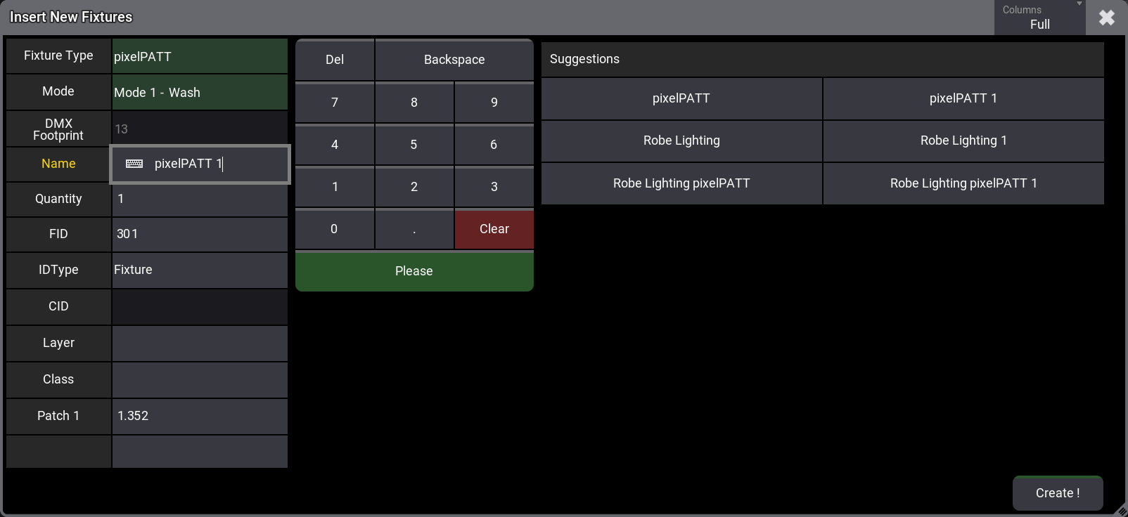
- All the fields in the right column can be filled with information. The required fields have a value suggestion. These can be edited to suit the needs. All the information can also be edited afterward in the patch menu. The area on the right side adapts to help fill out the selected field. It might have suggestions for input.
- Accept the suggested values, or edit them to suit the needs.
- Tap Create ! to add the fixtures.
A row now represents each new fixture in the patch menu. Read below for an explanation of each column in the patch menu and detailed information about changing some values.
Short Explanation of Each Column in the Patch Menu
The patch menu has a lot of columns. This is a short explanation of each. Remember that the patch menu has a condensed and full mode. Select Full to see all the columns.
- FID:
This is the Fixture ID of the fixture. Read more in the Assign an ID to fixtures below. - IDType:
This is the ID Type of the fixture. Read more in the Assign an ID to fixtures below. - CID:
This is the fixture's CID. Read more in the Assign an ID to fixtures below. - Name:
This is the name of the fixture. If there are sub-fixtures, then a right-pointed arrow can be tapped to unfold the sub-fixtures. - FixtureType:
This is the name of the selected fixture type. - Mode:
This is the mode of the selected fixture. - Patch:
This is the first DMX address of the fixture. Read more in the Assign DMX address to fixtures below. - Layer:
Fixtures can be organized in Layers. This is the layer information for the fixture. Read more in the Classes and Layers topic. - Class:
Fixtures can be organized in Classes. This is the class information for the fixture. Read more in the Classes and Layers topic. - Pan Offset:
This offset value can offset the DMX output for the Pan attribute. The offset value is applied just before the DMX output. This means the offset is not shown in the programmer, cues, or presets. The offset can be useful if, for instance, a fixture is hung differently than what has been programmed, especially in a touring situation where it is not a permanent change. - Tilt Offset:
This is the same as the Pan Offset, but for the tilt attribute. Read above. - Pan DMX Invert:
The Pan DMX output can be inverted by editing this field. This can be useful depending on how the fixtures are mounted. - Tilt DMX Invert:
The Pan DMX output can be inverted by editing this field. This can be useful depending on how the fixtures are mounted. - Pan Enc Invert:
Pan can be inverted for the encoder rotation by editing this field. This can be useful depending on how the fixtures are mounted. - Tilt Enc Invert:
Tilt can be inverted for the encoder rotation by editing this field. This can be useful depending on how the fixtures are mounted. - Pos X:
This is the fixture's position on the X-axis in the 3D window. - Pos Y:
This is the fixture's position on the Y-axis in the 3D window. - Pos Z:
This is the fixture's position on the Z-axis in the 3D window. - Rot X:
It is the rotation of the fixture on the X-axis in the 3D window. - Rot Y:
It is the rotation of the fixture on the Y-axis in the 3D window. - Rot Z:
It is the rotation of the fixture on the Z-axis in the 3D window. - Scale X:
This can scale the fixture/object on the X-axis in the 3D window. The scale value is a factor where 1 is the default. A higher number makes the object bigger. A smaller number makes it smaller. - Scale Y:
This can scale the fixture/object on the Y-axis in the 3D window. The scale value is a factor where 1 is the default. A higher number makes the object bigger. A smaller number makes it smaller. - Scale Z:
This can scale the fixture/object on the Z-axis in the 3D window. The scale value is a factor where 1 is the default. A higher number makes the object bigger. A smaller number makes it smaller. - Gel Color:
Here, a color that will be added to the output from the fixture can be defined. It is useful for adding gels to conventional fixtures. This is visualized in the console and 3D Viewer. - Gel:
This column does not currently have a function. - Note:
This adds a multiline note to the fixture. - Beam Angle:
Here, a beam angle can be defined for the fixture. This is useful for conventional fixtures where different angles might be needed. This is visualized in the 3D window. - Shadow Quality:
This setting defines the render quality of the shadows created when this fixture's light beam hits a different object that casts shadows. A higher level of quality improves the real-world look, but it also increases the calculations needed for the 3D visualization. The options are None, Low, Medium, High, and Very High.
Cast Shadows need to be set to Yes for the shadows to be rendered (see below). This setting is not available for environmental fixture types. - Cast Shadow:
Each fixture can cast a shadow or not. This setting defines if this fixture should cast a shadow. - Follow Target:
Turning this to Yes makes the fixtures or 3D objects something that can be selected or picked using the Follow function in the 3D Viewer. - Selectable 3D:
This is a Yes or No (text is hidden) field. Yes means that the fixture can be selected using the selection tool in the 3D Viewer. Turning this off (No option) for stage elements that do not need to be controlled can be useful. - Visible 3D:
This is a Yes or No (text is hidden) field. Yes means that it is shown in the 3D Viewer. - Target Space:
The MAker fixtures use this. This is the selected target space for the MArker fixture. It defines the available space where fixtures can move their light beams when selecting this MAker fixture. Learn more in the MAker Fixture topic. - Movement Space:
The MAker fixtures use this. This is the selected movement space for the MArker fixture. It defines the space wherein the MAker fixture can move. Learn more in the MAker Fixture topic. - Master React:
This setting has three options: None, Group, and Grand. This defines if the intensity is affected by a master. If Grand is selected, then group masters are also affecting the fixture. If Group is selected, then they are not affected by the grandmaster. None makes the fixture ignore both groups and grandmasters. - Appearance:
An appearance can be assigned to the fixture.
Assign an ID to Fixtures
The fixtures need at least one ID to be selected and controlled.
There are two types of ID numbers for each fixture. Fixtures can have both or just one of the two - but it needs at least one.
The FID is the default fixture ID. The number here is used with the Fixture keyword.
The CID is the second ID. This can be used if the IDType differs from "Fixture". Editing the IDType field opens the Select IDType pop-up.
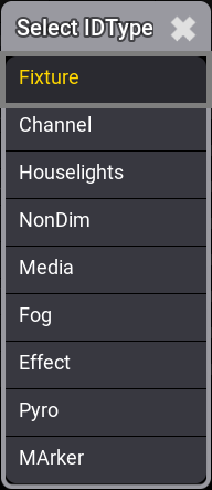
This lists the different valid IDTypes. Select one that is not "Fixture" to use the CID.
|
|
Important: |
| There are other hidden types called Universal and Multipatch. Universal is a special type the software automatically creates for a special universal fixture added to the patch. Multipatch is used for special multipatch versions of fixtures. These IDTypes cannot be used for normal fixtures. |
- Select the ID fields in one of the two ID columns (FID or CID) for the fixture rows where an ID is to be assigned. The selection order is important.
- Type a number on the keyboard and assign the number by pressing Please.
Now the fixtures have an ID. The numbers are assigned sequentially based on the selection order.
Assign DMX Address to Fixtures
The fixtures need to be assigned a DMX universe and address before being able to create any output.
There are two primary options to give the fixtures an address. One is to just type the desired address directly in the patch field. The other is to use the dedicated Edit Patch pop-up.
Type the number:
- Select the fields in the Patch column for the fixture rows where the address will be assigned. The selection order is important.
- Type the DMX universe and address separated by a dot (for example, 2.1) on the keyboard and assign the address by pressing Please.
Use the Edit Patch menu:
- Select the fields in the Patch column for the fixture rows where the address will be assigned. The selection order is important.
- Right-click the blue selected areas or tap the Patch button - this opens the Edit Patch pop-up.
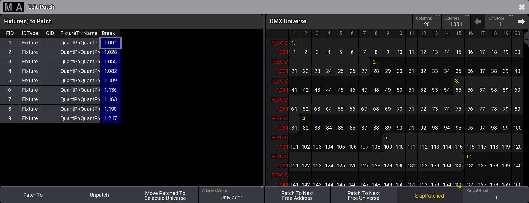
This pop-up is divided into two sides. On the left side, there are all the selected fixtures. On the right side is a view with all the DMX universes and addresses. The purpose of the menu is that fixtures can be selected on the left side, and the universe list on the right side shows where there is available space in the universes. There are several ways to navigate universes and assign the fixtures to the selected DMX address.
The numbers on the right side are red if the universe is not granted.
The pop-up also opens a dedicated encoder toolbar:

This toolbar can be used to select fixtures, universe, and address.
This is one way to do it:
- Select the fixtures in the correct order.
- Use the encoders to navigate to the desired address.
- Tap the Address encoder to assign the fixtures to the address.
The Edit Patch pop-up has several buttons at the bottom:
- PatchTo:
Opens a small pop-up where the desired patch address can be typed. - Unpatch:
This removes the patch address from the fixtures. - Move Patched To Selected Universe:
This moves the fixtures to the selected universe and keeps the DMX address. - AddressMode:
This toggle button changes how the DMX address is displayed. They can be split up into universes and a range DMX address from 1 through 512 - this option is called Univ.addr. The other option is Absolute, which shows the addresses continuously starting from number 1 and upwards. - Patch To Next Free Address:
This gives the fixtures the next available DMX addresses. - Patch To Next Free Universe:
This patches the fixtures to the next empty universe. - SkipPatched:
This will skip addresses that have patched fixtures when scrolling through the universes. - PatchOffset:
This can set the desired number of DMX channels between the fixtures. If the number is lower than the number of channels the fixtures use, they are patched as close as possible. If the number is more than the used channels, then the PatchOffset number is used.
The Edit Patch menu auto closes when all the selected fixtures are patched.
Filtering the Patch Menu
Filtering in the patch menu can be useful when there are a lot of fixtures and stage elements.
There are several ways to filter the fixtures in the patch menu.
An existing filter can be assigned using the Filter input in the title bar. Tapping this opens a small select pop-up that lists all existing filters (read about creating a filter in the Create a Filter topic). Two other options are None (no filter) and New (create new filter). Select the desired filter.
Filtering needs to be turned On for the filter to be active. Tap the filter icon (![]() ) (between Filter and Columns) to turn it On. This button toggles On or Off.
) (between Filter and Columns) to turn it On. This button toggles On or Off.
Turning filters On also exposes column filters. An extra row is displayed above the fixture rows just below the column titles. Any column value can filter the patch simply by editing the filter field for a column. Only one filter value can be applied to each column.
Edit a column filter field to assign a value. Some fields open a small selection pop-up giving a list of available values. Others are input fields where a text needs to be written.
The column filters can be combined with a filter from the pool.
The Split View is also a way to filter the patch. Learn more about the split view in the Patch and Fixture Setup topic.
Closing the Patch Menu
There is a pop-up asking what to do when exiting the patch menu.
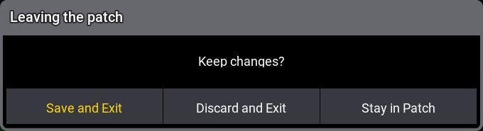
This asks if the changes should be kept.
Tap Save and Exit to save the changes and leave the patch menu. Tap Discard and Exit to cancel any changes and leave the patch menu. Tap Stay in Patch to stay in the patch menu.