3D Viewer
|
grandMA3 User Manual » Patch and Fixture Setup » 3D Viewer
|
Version 2.0
|
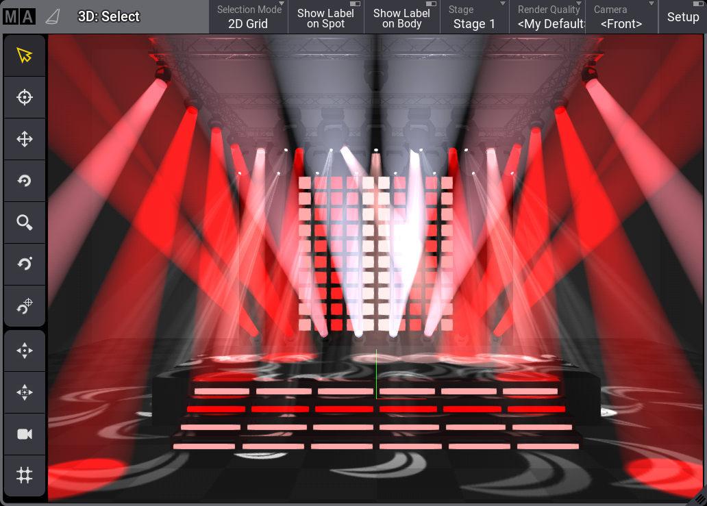
The 3D Viewer shows a 3D visualization of the virtual space where fixtures and 3D elements can be positioned and rotated.
The fixtures can project a light beam that moves and changes color when the values for the fixtures are changed.
All the fixtures and other stage objects can be positioned and rotated in the Patch, Live Patch, or using this window.
The Stage object can be visualized as a box or just a floor. The box can be looked into, but not out of. Read more below.
Fixtures can be interacted with in the 3D Viewer like the Fixture Sheet. For instance, it can be used in combinations with commands.
There are virtual cameras that are used to see the 3D space. These define the position, direction, and other settings from where and how the 3D space is viewed. The cameras are stored in the Camera Pool.
|
|
Restriction: |
| When on an onPC station, the driver of the GPU has issues with OpenGL, the 3D Viewer informs the user about the driver issue instead. In this case, the 3D Viewer does not try to render 3D scenes anymore. |
Title Buttons
There are several default buttons in the title bar. The available buttons in the title bar can be edited using the window settings. Learn more in the Title Bar Configuration topic.
Most of the default buttons are swipe buttons that open a list of the available options.
Three toggle buttons turn On or Off labels and turn On or Off the Setup mode.
The others give fast access to select Selection Mode, Stage object, Render Quality, and Camera selection.
There can be several stages in the patch. Each 3D Viewer can show one of these stages or all stages. Read more about stages in the Stages topic.
Read about all the settings below.
Left Side Tool Buttons
There can be a toolbar on the left-hand side of the window. These tools control what happens when the window is touched and change camera positions (read more about the cameras below).
The ones that change the touch mode are tapped to select the mode, and when the window is touched, the mode dictates what happens.
The selected mode is displayed with a yellow color in the window title bar. Most tools are grayed out and disabled if the selected camera is locked.
This is the explanation of the different tool buttons:
 (Select):
Sets the touch mode to Select. This is used to select fixtures in the window. The fixtures can be tapped or selected using a selection lasso. (Follow):
Sets the touch mode to Follow. This makes all the selected moving lights point to the touched stage area. The follow function obeys the Align settings. (Move):
The mode is set to Camera Move. Move means changing the camera's position without changing the camera's pan and tilt values. The scroll wheel on a mouse moves the camera forward and backward in the view based on the location of the pointer (not necessarily the center). (Rotate Center):
Sets the mode to Camera Orbit. This mode orbits the camera around the center of the window, keeping it pointed toward the center. The scroll wheel on a mouse moves the camera closer to or away from the location of the pointer (not necessarily the center). (Zoom):
Changes the mode to Camera Zoom. This mode moves the camera in and out of the 3D Viewer. This can also be done in the other modes using a scroll wheel on a mouse. (Rotate Pivot):
Changes the mode to Camera Pivot. This pivots the camera around a pivot point that does not have to be the center. The pivot point can be set (read about the next button) and is remembered until a new point is set. The scroll wheel functions just like the rotate center mode. (Set Pivot):
This button is used to set a new pivot point in the window. The rotate pivot mode is selected as soon as the point has been set (by clicking or touching the window). (Focus) - only available when Setup is On:
This tool can focus static fixtures (fixtures without position attributes). Select the desired fixture, tap this tool, and tap the location in the 3D Viewer where the fixture should be pointed. This tool affects the rotation values of the fixture. (Fit):
Tapping this button moves the camera to fit the entire stage area into the view. (Fit Selected):
Tapping this button moves the camera to fit the selected fixtures into the view without orbiting the camera. (Camera):
This button reloads the selected camera to the settings set in the camera pool object. (3D view to Selection Grid):
Tapping this tool creates grid values for the Selection Grid, using the current view of the fixtures.
Moving the Camera
The cameras are pool objects in the Camera Pool. A camera can be moved to different locations and pointed in different directions.
This information can be edited in the pool, but the position and direction are easier to change in the 3D Viewer - read about the left-hand side tool buttons above.
A scroll wheel on a mouse moves the camera closer to or away from the location of the pointer.
Editing the camera in the pool allows changing the camera mode and type. Read more in the camera pool topic (link above).
Moving the Fixtures
The fixtures' position and rotation can be set in the patch or live patch. But they can also be positioned live in the 3D Viewer.
Read more about this in the Position Fixtures in the 3D Space topic.
3D Viewer Settings
The settings can be opened by tapping the MA logo in the upper left corner of the 3D Viewer.
This opens a settings pop-up. This pop-up has tabs called Rendering, Misc, and Label.
Rendering Settings
The rendering settings are about light levels, colors, and rendering quality.
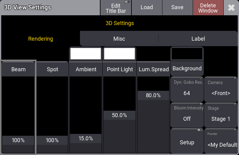
There are four on-screen faders:
- Beam:
This is the visibility of the light beam from all fixtures. - Spot:
This is the general intensity of the visualization of the light beam reflection where it hits a surface. - Ambient:
This is the ambient light level inside and outside the stage box. It is a very diffuse light that removes some of the contrast in the 3D Viewer. - Point Light:
This is a light source from the direction of the camera. It is used to light up the elements in the 3D space. - Lum. Spread (Luminous Spread): This controls how visible the difference in brightness between different fixture types is. The fixture type with the highest luminous intensity defines this intensity as 100% brightness in the 3D Viewer window. When fixture types are used that have a much lower Luminous Intensity, they will be rendered much darker at their 100% dimmer output.To allow adjustment to this intensity difference (and therefore deviate from reality) to better see the darker fixture, the Luminous Spread setting can be used with different values:
- When this setting is set to 100%, the Luminous Intensities are rendered as before.
- Setting the Luminous Spread to 0% renders all fixtures beams with the same maximum brightness.
- The default of Luminous Spread in the 3D Viewer window settings is set to 80%.
The ambient and point light can be colored, similar to putting a gel in front of the light. The area above the faders can be tapped to open a color selector pop-up.
The Background can also be colored. The ambient light must be turned up for this color to be visible.
There are some buttons:
- Dyn. Gobo Res. (Dynamic Gobo Resolution):
This is the resolution of dynamically created gobos. - Bloom Intensity:
The blooming effect can be turned On or Off. Tapping this button toggles between the two. - Setup:
Turning the setup On makes it possible to move the fixtures and 3D objects using the 3D Viewer and encoder bar. Read more about this in the Position Fixtures in the 3D Space topic. - Camera:
This is used to select one of the cameras from the camera pool. If it is set to follow the selected camera, the name is inside angled brackets. Read more about cameras in the Camera Pool topic. - Stage:
This selects what stage the 3D Viewer shows. A single stage can be selected, or all stages can be shown. Read more about stages in the Stages topic. - Render:
This is used to select one of the render qualities. Read more in the Render Quality topic.
Some of these are swipe buttons, so remember that the options can be reached easily by swiping out of the button.
Misc Settings
The second tab is called Misc.
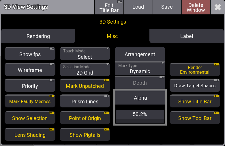
The Misc. tab has the following settings:
- Show fps:
Turning this On displays frames per second information in the upper right corner of the window. - Wireframe:
Turning this On shows the 3D Viewer as a wireframe instead of a shaded view. - Priority:
Turning this On gives the 3D Viewer a high priority. It is only recommended to turn this On when used on a computer with a high-quality graphics card. It takes away resources from a console interface, making it react slower to user input. - Mark Faulty Meshes:
This marks meshes that are unloaded or faulty. - Show Selection:
Selected fixtures are marked with a yellow body color for the primary fixtures and a light red color for multipatch fixtures when this is On. Learn more about multipatch in the Add Multipatch Fixtures topic. - Lens Shading:
This defines whether the selection is shown on the lens of a geometry type “Beam”. The shaded selection is drawn when it is On. - Touch Mode:
Touching and swiping in the 3D Viewer can interact with the window differently. This setting defines how. Tapping it toggles through the following options: Select, Follow, Focus(Only valid when Setup is On), Camera Orbit, Camera Zoom, Camera Pivot, Camera Move, and Camera Set Pivot.
The Camera options move the camera - Read more above. The Select option is used to select fixtures in the view. - Selection Mode:
This defines how the fixtures are selected and positioned in the Selection Grid. The selection mode has two different options:- 2D Grid:
The 2D grid selection offers two different modes, Planar and Perspective. Using the lasso selection to select fixtures in the 3D Viewer adds them as a two-dimensional selection to the selection grid. In planar mode, the camera position does not affect the selection order. Only the real position of the fixtures is significant. In perspective mode, the camera's orientation also influences the selection's order in the selection grid.To select fixtures in the 3D Viewer using the planar selection, draw a lasso starting with a horizontal or vertical mouse movement. The color of the lasso changes to green when the selection is locked to planar mode. To select fixtures in perspective mode, draw a lasso starting with a diagonal mouse movement. The color of the lasso changes to cyan when the selection is locked to perspective mode.
- Linearize:
The selection is linearized to only the X-axis of the selection grid depending on which direction the selection lasso was created (top/bottom - left/right). This selection mode is indicated with a yellow lasso.

Hint: The projection distortion of the camera of the 3D Viewer may affect the position of the fixtures in the selection grid if the perspective selection is used. To prevent this, use a 2D camera in the 3D Viewer. - 2D Grid:
- Mark Unpatched:
This marks the body of unpatched fixtures with a dark red color when On. - Prism Lines:
This shows a line for each prism facet when the Beam Quality is set to Line. - Point of Origin:
This shows a point of origin axis marker. It is typically at the zero point of the stage. - Show Pigtails:
This shows the "Pigtail" element if the GDTF model defines it. - Arrangement:
This is a collection of settings for visualizing the purple arrangement "ghosts" markers. They are seen when using the arrangement tool to position fixtures.- Mark Type:
There are two options: Dynamic or Small. Dynamic shows a box matching the size of the fixture. Small is just a small square marker. - Depth:
Set if the depth of the 3D space is considered when showing the marks. This could lead to marks being hidden behind objects. If the depth is switched off, the marks are always drawn in front of other objects. - Alpha:
Define the transparency of the marker objects.
- Mark Type:
- Render Environmental:
This toggles if the environmental elements are rendered or hidden. - Draw Target Spaces:
This setting show or hide a square wireframe for MArker fixtures' target spaces. - Show Title Bar:
This setting shows or hides the title bar for the window. - Show Tool Bar:
This shows or hides the toolbar on the left-hand side. The toolbar is always visible when Setup is On.
Label Settings
The tab is called Label. It is settings about the labels that can be turned On or Off for the spots and the fixture bodies.
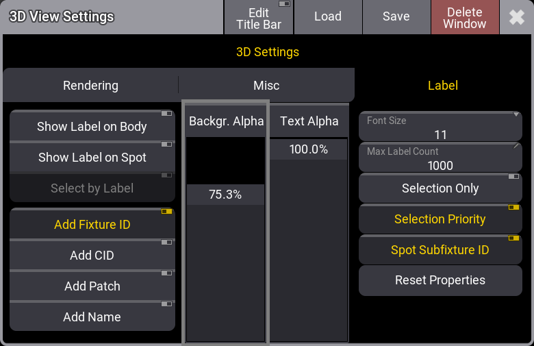
- Show Label on Body:
This On / Off button enables labels to be drawn on the fixture's body. - Show Label on Spot:
This On / Off button enables labels to be drawn in the center of the fixture's spot. A fixture can also be selected using the rubber band selection on a label. - Select by Label:
This setting is possible when Show Label on Spot is active. It makes it possible to select fixtures by selecting the spot labels in the 3D Viewer when this setting is On. - Add Fixture ID / Add CID / Add Patch / Add Name:
These On/ Off buttons define the information displayed on the label. - Background Alpha:
This on-screen fader sets the transparency of the label's background. - Text Alpha:
This on-screen fader sets the transparency of the text displayed on the label. - Font Size:
This button sets the font size of the text displayed on the label. Tapping this toggles through the available Font Sizes. It can be swiped to open a small Select Label Font Size pop-up with all the size options. - Max Label Count:
This input field sets the maximum count of labels that are displayed at the same time. If the number of labels exceeds the maximum label count, the labels closest to the camera will be displayed. - Selection Only:
This On / Off button defines whether labels are displayed for all fixtures or only for selected or partly selected fixtures. - Selection Priority:
This On / Off button defines whether labels of selected fixtures are displayed on top of not selected fixtures. - Spot Subfixture ID:
This On / Off button defines if the label of the spots shows the Fixture ID of the corresponding sub fixture (On). Otherwise, all spots of a fixture show the Fixture ID of the main fixture (Off). - Reset Properties:
Tap this button to reset the label properties to their factory defaults.
Setting Up a 3D Computer
The grandMA3 consoles can show a 3D Viewer with the fixtures and the stage setup. But the consoles are optimized to be the human interface used to program the light.
If a high-quality and high-framerate 3D render machine is needed, the best solution is to have a high-performing computer with good graphics cards. This computer must have the grandMA3 onPC installed and optimized for 3D graphics.
The grandMA3 onPC needs to be in a session with the console. The grandMA3 onPC could be logged in as the default 3D user who uses a different Screen Configuration (read about screen configurations in the User Settings topic) but is the same user profile as the default admin user. The grandMA3 onPC should be logged in with a user with the same profile as the user looking at the 3D computer. This ensures that the 3D computer follows the user into preview mode.
The 3D computer could have one big 3D Viewer with all the render settings set to the best quality, and the 3D Viewer setting called Priority should be On (see settings above).
The window can also be set to hide the title bar to maximize 3D viewing space using the Window Settings. Other elements, like the view buttons, encoder bar, etc., can also be hidden using the Configure Display pop-up.