|
grandMA3 User Manual » Phasers
|
Version 2.1
|
Phasers are the effects and chasers of grandMA3, creating dynamic output from a single preset or cue.
Phasers change the output for attributes using a set of information in two or more steps. A normal, static cue or preset only contains one step of information. Adding additional steps creates a phaser.
Example
A phaser has two steps with an absolute dimmer value of 100% in step 1 and an absolute dimmer value of 0% in step 2. With all other phaser layers at their default values, the resulting output is a smooth, repeating fade of the dimmer output from 100% to 0% and back to 100%.
Layers
Value Layers
Each phaser step can include attribute value information. These values can be an absolute value (for instance, a dimmer value of 50%) or a relative value (for instance, a dimmer value of -20%). Steps can contain both absolute and relative values simultaneously.
|
|
Important: |
| The grandMA3 software handles storage, editing, and playback of absolute values and relative values separately. This separation allows the user to combine different absolute and relative values as desired. |
Step Layers
Each phaser step also includes additional layers, which define the overall width of the step, the percentage of the step dedicated to transitioning to the new value, and the amount of acceleration and deceleration used when changing to the new value.
- Width
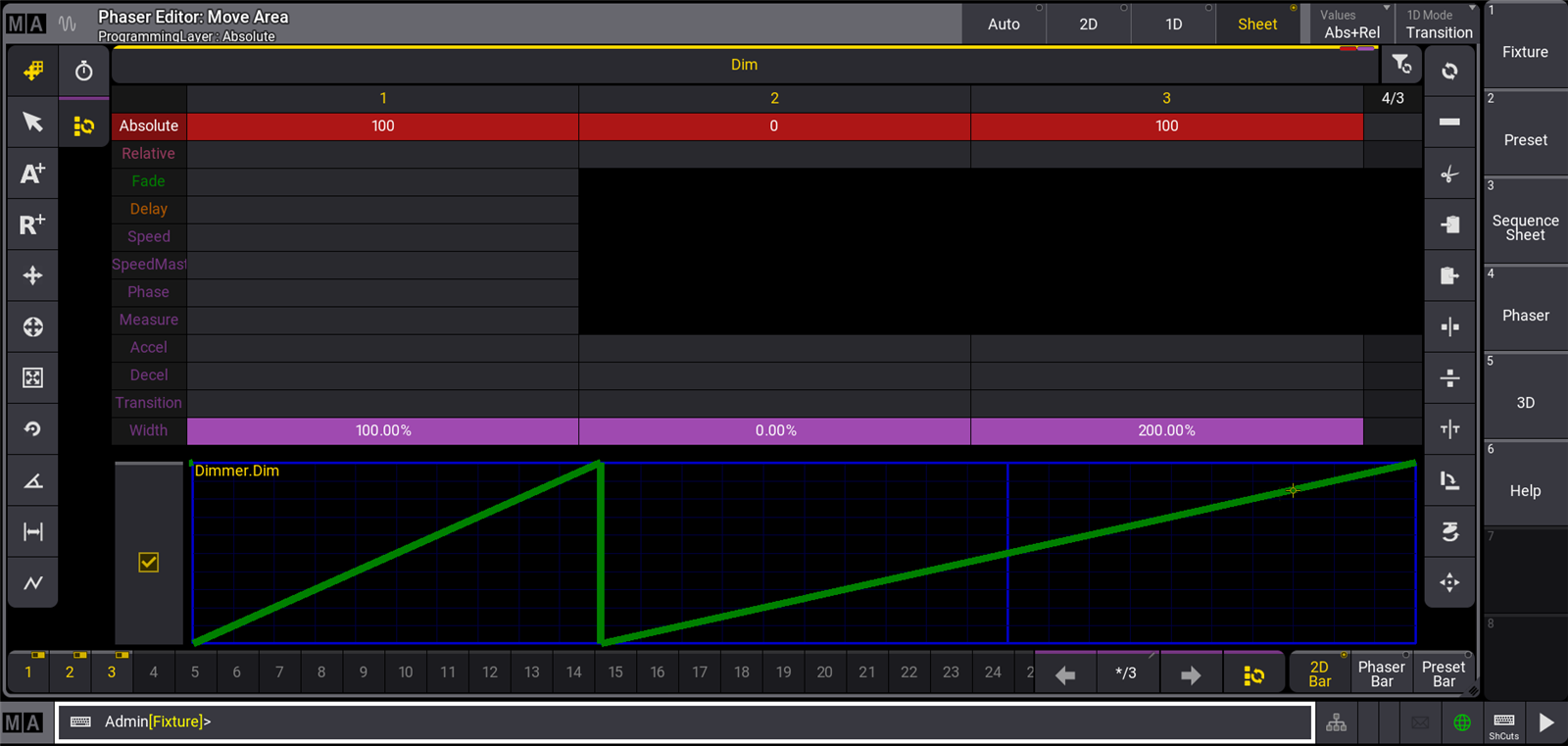
The Width layer defines the total amount of time from the beginning of a step to the beginning of the next step. Width is shown as a percentage of one beat as defined by the Speed layer. The image above shows the first step with 100% width, so the change in value takes place over the time of one beat. The second step has a width of 0%, so the values change instantaneously and the next step begins immediately. The third step has a width of 200%, so the values change over the time of two beats.
- Transition
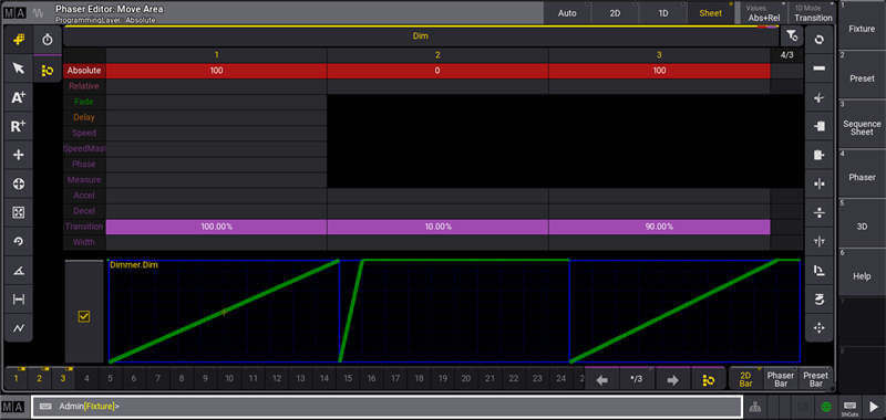
The Transition layer defines how much of the step width is used to adjust values to their new levels. The transition of a step is shown as a percentage of the width of that step. The image above shows the first step with a transition of 100%, so the values change during the entire time of the step. The second step has a transition of 10%, so the values change during the first 10% of the width of the step, then remain at the new level until the end of the step. The third step has a transition of 90%, so the values change during the first 90% of the width of the step, then remain at the new level until the end of the step.
- Accel
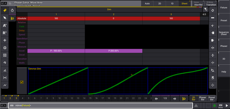
The Accel layer defines how abruptly or gently the attributes begin to change from the value defined by the current step toward the value of the next step (acceleration). In the image above, the first step shows an acceleration of -100%, resulting in a smooth start to the transition away from the value at the end of the step. The second step shows an acceleration of 200%, resulting in an abrupt start to the transition away from the value at the end of the step.
- Decel
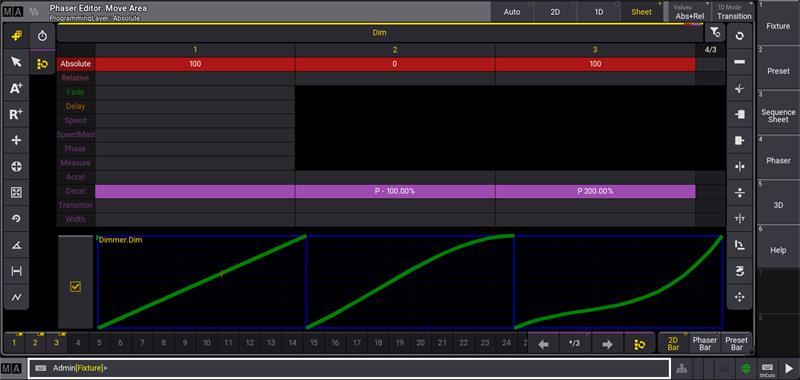
The Decel layer defines how abruptly or gently the attributes reach the value defined by the current step (deceleration). In the image above, the second step shows a deceleration of -100%, resulting in a smooth end to the transition into the value for the step. The third step shows a deceleration of 200%, resulting in an abrupt end to the transition into the value for the step.
|
|
Hint: |
| For linear transitions, keep Accel and Decel values at 0%. For smooth transitions, closely resembling sinus or cosinus waves, Accel and Decel values of -100%. |
Phaser Layers
Each phaser additionally includes layers, which affect all steps of the phaser. Each attribute of each fixture can have its own speed, speed master, phase, and measure value in a phaser, but these values will be the same for all steps in a phaser.
- Speed
Speed defines the overall rate at which the console plays back the steps of a phaser. The grandMA3 displays speed in units of either BPM (beats per minute), Hz (beats per second), or Seconds (seconds per beat).
- SpeedMaster
SpeedMaster defines per attribute to which master of the type speed the phaser adapts its speed to. Phasers speeds can be assigned to executors by using speed masters. For more information, see SpeedMaster keyword.
- Phase
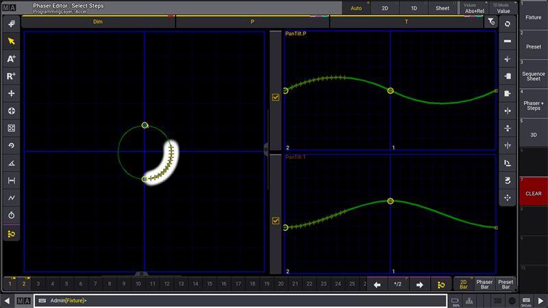
Phase defines the timing offset of each fixture's attributes within a phaser. Phase is displayed in degrees (º). The image above shows a selection of fixtures in a circle phaser with phase offsets ranging from 0 to 90 degrees. The Phaser Editor displays this offset in both the 2D and 1D layouts.
- Measure
The optional Measure layer defines the number of beats in the repeating phaser loop. For example, a phaser with a measure of 4 beats and a speed of 120BPM will repeat every 2 seconds.
|
|
Hint: |
| When using the Measure layer, multiple combinations of step widths can produce the same result. In this case, it may be easiest to think of the width as a percentage of one beat in the measure. |
All phaser layers, as well as a step selection tool, appear in the Encoder Toolbar any time attributes are mapped to the encoders. Phaser layers are indicated by a dark purple color. Phaser layers behave just like other attribute layers when activating, deactivating, storing, and clearing. For more information about attribute encoders and layers, see the Operate Fixtures topic. The Phaser Editor provides a graphical view and powerful manipulation of phaser layer information.
Steps
The grandMA3 offers multiple tools and methods for creating, selecting, and deleting phaser steps.
One intuitive method to quickly create steps based on presets involves the Step key. To create steps using this method, press and hold the Step key, then tap a preset for each desired step.
Example
To create a 3-step color phaser from white to red to blue:
- Select the desired fixtures.
- Press and hold the Step key.
- Tap the white color preset.
- Tap the red color preset.
- Tap the blue color preset.
- Release the Step key.
When using this method, the software will only create the next step when tapping a new preset, which contains any of the same attributes as the current step. This behavior allows each step to reference multiple presets as long as those presets apply to different attributes.
Example
To create a 2-step phaser, where each step contains both color and position presets:
- Select the desired fixtures.
- Press and hold the Step key.
- Tap the desired color preset for step 1.
- Tap the desired position preset for step 1. This preset is added to step 1.
- Tap the desired color preset for step 2. Step 2 is automatically created.
- Tap the desired position preset for step 2. This preset is added to step 2.
- Release the Step key.
The Step key can also quickly change which preset is referenced by a step.
Example
Start with the 3-step color example above, but afterward, change the blue step to yellow:
- Follow all directions in the 3-step color example above.
- Press and release Step.
- Press and release 3.
- Tap the yellow color preset.
Delete specific steps from the programmer using standard syntax with the Delete keyword. For example, to delete step 3, type:
|
|
User name[Fixture]>Delete Step 3 |
Alternatively, delete specific steps from the programmer by selecting the steps in the Step Bar and deleting the programmer.
|
|
User name[Fixture]>Delete Programmer |
An easy way to access this command (especially on grandMA3 onPC) is to tap Delete Steps in the At Overlay.
Stomp
The stomp function stops a phaser, running either in the programmer or from a playback, and resolves the stomped attributes to a single, static step. The console calls and activates the last static output value for each stomped attribute into step 1 of the programmer. All other steps of the stomped phaser are discarded.
With the programmer in step 1, calling a static preset onto any attributes currently running in a phaser automatically uses the stomp function to stop the phaser and output only the static look from the preset. Phasers follow this behavior whether the static preset is called directly in the programmer or as part of a recipe.
Sync
The Sync option ensures that phasers recall with predictable timing and phase offsets.
When calling phasers into the programmer, the Sync option is available in the Encoder Bar.
When recalling phasers stored in cues, the Sync option is available as a setting for each cue part in the Sequence Sheet. For more information about settings in cues and cue parts, see the Look at Cues and Sequences topic.
DelayToPhase
The DelayToPhase setting links the phase calculation of a phaser to any active individual delay time for the attribute.
When enabled, the phase calculation for each attribute begins as the values start to change at the end of the delay time. Because this delay timing may be different for different attributes or fixtures within a single cue, the resulting output may appear to include different phase offsets than originally stored within the phaser.
When disabled, the phase calculation for all attributes starting a phaser in the same cue starts when the cue is triggered, regardless of any individual delay times. This allows for more predictable, synchronized phaser playback, even with different individual delay times.
The DelayToPhase setting applies to all phasers in the show and appears in the Timing tab of the Preferences and Timing menu.