
MIDI Show Control (MSC)
MIDI Show Control (MSC) is a different way to remote control the system.
It was released in 1991 as an extension to the MIDI protocol. The grandMA2 system is capable of receiving and transmitting MSC.
There are a lot of settings to MSC. Most of these are setting to be able to match the transmitting and receiving devices. Please read below.
Below the settings there is a description of the MSC concept and then some words about transporting MIDI using Ethernet.
Setting up MSC
To access these settings, press the Setup key and then the Midi Show Control button under the Console tab.
The settings could look like this:
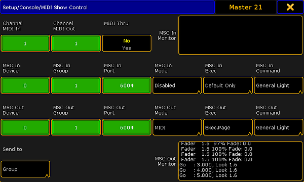
There are four rows with different settings and two monitor fields.
The monitor fields display the incoming and outgoing MSC. They display the data as interpreted data, meaning that it does not show the raw hex data.
The top row has two input fields and one toggle button:
- Channel MIDI In:
There are 16 different channels in MIDI. The number in the In field needs to match the channel number from the transmitter. - Channel MIDI Out:
The channel number in this field need to match the channel number of the MSC receiver. - MIDI Thru:
This toggle button turn On or Off is any incoming MIDI should also be sent out of the MIDI output.
If MSC commands are transmitted and received on the same MIDI channel, then a loop will be created.
The next two lines are the same except the first is the settings for any incoming MSC and the second is the outgoing MSC.
- Device:
There are 112 different devices in MSC. MSC also specifies an "All" option. This is set in the Send to button at the lower left corner - read about it below. This input accepts values from 0 to 111. - Group:
The MSC standard has the option to organize the devices in 15 different groups. Here it is possible to set a group number from 1 to 15. Please read about the Send to setting below. - Port:
If MSC is to be sent using an Ethernet connection, then there needs to be an IP port number. This can be set here. The default number is 6004. The port number needs to be between 6000 and 6100. - Mode:
Tapping here opens a Select MSC Mode pop-up: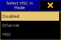
Select MSC (In) Mode pop-up
There are three options here:- Disabled - this is the same turning off the MSC input or output.
- Ethernet - This will use MSC via Ethernet - Please read more about MSC via Ethernet below.
- MIDI - This will use the MIDI ports on the station to transmit or receive MSC.
- Exec:
Tapping here opens the Select MSC Exec pop-up: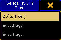
Select MSC (In) Exec pop-up
There are three options here:- Default Only - This option will make the MSC commands go to and from the selected executors on the Master station only.
- Exec.Page - This option can be used if the commands should be sent to a specific executor. The page and executor number must be separated by a "period" character (Hex = 2E).
- Exec Page - This option can be used if the commands should be sent to a specific executor. The page and executor number must be separated by a "NULL" character (Hex = 00).
- Command:
Tapping here opens the Select MSC Command pop-up: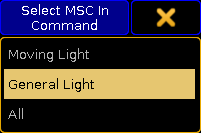
Select MSC (In) Command pop-up
There are three options here:- Moving Light - This option will select moving light command format (hex 02).
- General Light - This option will select the general lights command format (hex 01).
- All - This will use the all type format (hex 7F).
The button in the fourth row is called Send to. Tapping it open a Select Send to pop-up like this:
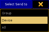
There are three options:
- Group:
Selecting this will make the station transmit MSC to the specified group number (1 to 15). - Device:
Selecting this will make the station transmit MSC to the specific device number (0 to 111). - All:
This option will transmit the the MSC to all connected devices.
The MSC Concept
The MSC command structure and syntax is based on the general SysEx structure defined by MMA (MIDI Manufacturers Association). It was released in 1991 as an extension to the general MIDI.
The raw MIDI information is written in hex octets (two hexadecimal numbers). Different software manufacturers might present the MSC in an interpreted way and show the data in a more human readable form. This can of course be nice, but since we cannot describe every way this can be presented, this manual is looking at the raw data.
The message format looks like this:
| F0 7F | Device ID | 02 | Command Format | Command | Data | F7 |
|---|---|---|---|---|---|---|
- F0 7F is the header that identifies the message as "universal system exclusive" and a "real time" message.
- Device ID is the device or group number.
- 02 is a hex octet specifying that the message is MSC.
- Command Format is an octet that specifies the equipment type.
- Command is an octet that defines the command type
- Data is the actual data. This might change depending on the command type.
- F7 is a closing octet finishing the message.
Device ID
The device ID is an octet actually divided into three different sections:
- 00 to 6F:
This is the 112 different specific devices that can be identified. - 70 to 7E:
This is the 15 group numbers. - 7F:
This is a broadcast ID that all devices listen to.
In grandMA2 the device ID and group ID can be set for both incoming and outgoing messages.
For transmitting MSC it can only transmit one octet in the Device ID location. The Send to setting (described above) selects which one of the three different sections Id that should be transmitted.
Command Format
The command format octet denotes the type of equipment that should receive the message (or at least respond). grandMA2 only transmit and respond to three different formats:
- 01:
This is the General Lighting format - 02:
This is Moving Lights format. - 7F:
This is an All format that all equipment should respond to.
Command
The command octet denotes the type of command in the message. The command type will dictate the data information.
grandMA2 supports 7 different command types:
- 01 (Go):
This is the same as a Goto command in grandMA2. It needs to be followed by a cue number. - 02 (Stop):
This is the same as a Pause command in grandMA2. This can be followed by a cue number. - 03 (Resume):
This will "un-plause" a cue. If a specific cue has been paused, then the cue number needs to be specified with this command. - 04 (Timed_Go):
This can be used to perform a Goto with a specific fade time. It needs both the time and the cue number - in that order. - 06 (Set):
Set can be used to set the position of faders. It needs the fader number and page followed by the position. - 07 (Fire):
This can be used to trigger macros. The macro number needs to follow the command. Only macro 1 to 255 can be triggered. - 0B (Go_Off):
This command can be used "Off" executors. This needs to followed by a cue number.
Data
01 (Go):
As stated above: This is interpreted as a GOTO command. A cue number needs to be specified. The cue number also needs to be transmitted in hex octets and the complete cue number including the decimals needs to be transmitted. If cue number 4 is to be triggered then the complete number is 4.000 - the number with all decimal numbers separated by a dot (Hex value 2E). Decimal numbers in hex is some of the easiest to convert. It needs a "3" in front. This means that decimal 4 becomes 34 in hex. The complete cue number including the dot is then: 34 2E 30 30 30.
See this table for a complete decimal to hex translation.
If the station is set to Default Only in the Send MSC In Exec option, then this all that needs to be added after the command.
Example: Triggering cue number 21.5 on the default executor (All Devices, All Format, and Default Only setting):
| F0 7F | Device ID | 02 | Command Format | Command | Data | F7 |
|---|---|---|---|---|---|---|
| F0 7F | 7F | 02 | 7F | 01 | 32 31 2E 35 30 30 | F7 |
If the setting is not Default Only, then an executor and page needs to be specified. There are two options for separating the executor number and the page number. It can be separated by a "period" character (hex = 2E) or by a "NULL" character (hex = 00). The cue number and the executor/page data needs to be separated by a "NULL" character (hex = 00).
Example: Triggering cue number 37.2 on executor 5 on page 1 (All Devices, All Format, and Exec.Page setting):
| F0 7F | Device ID | 02 | Command Format | Command | Data | F7 |
|---|---|---|---|---|---|---|
| F0 7F | 7F | 02 | 7F | 01 | 33 37 2E 32 30 30 00 35 2E 31 | F7 |
Same example but with a "Null" separated executor and page:
| F0 7F | Device ID | 02 | Command Format | Command | Data | F7 |
|---|---|---|---|---|---|---|
| F0 7F | 7F | 02 | 7F | 01 | 33 37 2E 32 30 30 00 35 00 31 | F7 |
02 (Stop):
This is like hitting the pause button. Please read the section above for a better understanding of the hex cue numbering system.
With the Default Only option there does not need to be any extra data since it is the executor that is paused.
Example: Stopping the default executor (All Devices, All Format, and Default Only setting):
| F0 7F | Device ID | 02 | Command Format | Command | Data | F7 |
|---|---|---|---|---|---|---|
| F0 7F | 7F | 02 | 7F | 02 | F7 |
If the station is transmitting MSC, then it will transmit a cue number 0.000. This is like sending a “pause running cue” command.
If the settings are not Default Only but one of the two Exec/Page options, then the cue 0 also needs to be transmitted.
Example: Stopping executor 5 on page 1 (All Devices, All Format, and Exec.Page setting):
| F0 7F | Device ID | 02 | Command Format | Command | Data | F7 |
|---|---|---|---|---|---|---|
| F0 7F | 7F | 02 | 7F | 02 | 30 2E 30 30 30 00 35 2E 31 | F7 |
03 (Resume):
This is the only way to continue a paused cue. The only difference between the Stop and Resume commands are the “02” and “03”.
Example: Continuing the fade paused above (All Devices, All Format, and Exec.Page setting):
| F0 7F | Device ID | 02 | Command Format | Command | Data | F7 |
|---|---|---|---|---|---|---|
| F0 7F | 7F | 02 | 7F | 03 | 30 2E 30 30 30 00 35 2E 31 | F7 |
If the Default Only setting is chosen then the command is F0 7F 7F 02 7F 03 F7 to continue the fade.
04 (Timed_Go):
This is the same as the 01 (Go) command but with a specified time. Please read (and understand) about the 01 (GO) command and data above. Just to make this a bit simpler we are going to pretend that the “Default Only” option is turned on in the MSC options in Setup.
To transmit a timed Goto the time needs to be specified first and then the cue number. The time is specified by five hex octets. They represent (in order) Hour, Minute, Second, Frame, and Fraction.
The hour, minute, and second sections are very strait forward. The number needs to be transmitted in hex numbers. It is possible to transmit a value above the normal limit for example 64 seconds (hex = 40). The station will transmit this as 1 minute and 4 seconds.
Right now the console will not accept any time specified in the Frame and Fraction sections. But it transmit values below a second in the Frame section. The console divides the second into 24 frames. So 0.5 seconds is 12 Frames and the received hex number would be 0C.
Example: Goto cue 75 with the fade time of 20 seconds (All Devices, All Format, and Default Only setting):
| F0 7F | Device ID | 02 | Command Format | Command | Data | F7 |
|---|---|---|---|---|---|---|
| F0 7F | 7F | 02 | 7F | 04 | 00 00 14 00 00 37 35 2E 30 30 30 | F7 |
Example: Goto cue 5.4 with the fade time of 1 minute on executor 3 on page 1 (All Devices, All Format, and Exec.Page setting):
| F0 7F | Device ID | 02 | Command Format | Command | Data | F7 |
|---|---|---|---|---|---|---|
| F0 7F | 7F | 02 | 7F | 04 | 00 01 00 00 00 35 2E 34 30 30 00 33 2E 31 | F7 |
06 (Set):
The set command is used to move a fader to specific position. The 06 command is followed by two hex octets that indicates the fader and then two more octets that dictates the position.
The first of the two numbers for the fader is the fader number (on a page). The fader number 1 is hex number 00, the second is 01 and so on. Remember that this is a hex number so fader 16 have hex number 0F and decimal 17 is hex 10.
The second of the two numbers for the faders are the page number. This is a little different page 1 is hex number 01and page 2 is hex 02 and so on.
So executor 1 on page 1 is 00 01.
Calculating the position in hex numbers is a bit more tricky. The faders position is defined by a coarse and fine value. The scale for both values is 128 steps (most MIDI is in 128 steps). The fine value is transmitted first followed by the coarse value.
The desired fader position (in decimal) need to be multiplied by 1.28. The resulting integer is the coarse value. The remainder (everything on the right side of the separator) should be multiplied by 128 to get the fine value. The two decimal numbers then needs to be converted to hex.
Example:
The fader 3 on page 2 needs to be moved to 45%. First convert the position.
- Multiply 45 by 1.28 = 57.6
- Coarse value is 57.
- Multiply 0.6 by 128 = 76.8
- Fine value is 76.
- Convert decimal 57 to hex = 39.
- Convert decimal 76 to hex = 4C.
- Fine is transmitted before coarse so the position is: 4C 39
The MSC message is (All Devices and All Format setting):
| F0 7F | Device ID | 02 | Command Format | Command | Data | F7 |
|---|---|---|---|---|---|---|
| F0 7F | 7F | 02 | 7F | 06 | 02 02 4C 39 | F7 |
A fade time can be added after the fader and position data. The time format explained in the 04 command is used.
Example: Moving fader 15 on page 1 to 100% in 5 seconds (All Devices and All Format setting):
| F0 7F | Device ID | 02 | Command Format | Command | Data | F7 |
|---|---|---|---|---|---|---|
| F0 7F | 7F | 02 | 7F | 06 | 0E 01 7F 7F 00 00 05 00 00 | F7 |
The console only transmit the position of some faders - executors with sequences and all the green colored special masters (for the selected executor), but it accepts positions for all faders that have something assigned.
07 (Fire):
Macros can be fired by this command. It needs to be followed by a single octet specifying the macro number.
Macro number 1 is hex number 01. Hex number FF is macro number 255.
Example: Triggering macro number 64 (All Devices and All Format setting):
| F0 7F | Device ID | 02 | Command Format | Command | Data | F7 |
|---|---|---|---|---|---|---|
| F0 7F | 7F | 02 | 7F | 07 | 40 | F7 |
0B (Go_Off):
Executors can be turned off using the 0B command. A cue number needs to be transmitted - cue 0 can be used.
Example: Send an Off command to executor 9 on page 5 (All Devices, All Format, and Exec.Page setting):
| F0 7F | Device ID | 02 | Command Format | Command | Data | F7 |
|---|---|---|---|---|---|---|
| F0 7F | 7F | 02 | 7F | 0B | 30 2E 30 30 30 00 39 2E 35 | F7 |
MIDI via Ethernet
MSC can sent using Ethernet. It is transmitted as a UDP message.
The MSC message is the same as described above, but the MSC message needs a header for the date to be accepted by the grandMA2.
The header separated into two parts. The first is identifying the message as a grandMA2 MSC message: 47 4D 41 00 4D 53 43 00 - it translates to GMA MSC.
The second part is four octets describing the length of the message - including the header. It is written as little endian byte format (least significant first).
This is calculated by counting the number of octets and then convert the decimal number into hex. Usually we only needs the first octet (it allows for messages up to 255 octets) although all four needs to be sent.
Examples:
Send a go command to cue 35. The MSC message is: F0 7F 7F 02 7F 01 33 35 2E 30 30 30 F7.
This is 13 octets. The header is always 12 octets. So the combined length is 25 octets. Decimal 25 is 18 in hex. The entire message is:
47 4D 41 00 4D 53 43 00 18 00 00 00 F0 7F 7F 02 7F 01 33 35 2E 30 30 30 F7
Trigger macro 1 is: F0 7F 7F 02 7F 07 01 F7 - 8 octets.
Plus the 12 from the header is decimal 20 = 13 hex.
The message is:
47 4D 41 00 4D 53 43 00 13 00 00 00 F0 7F 7F 02 7F 07 01 F7