grandMA2
Version 3.9

Connect Analog Remote Control

To use the analog remote control, connect a contact closure switch e.g., a light barrier or a push button.

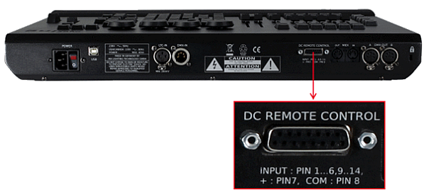
Generate a switch that sends between +5 and +15 volts to pin 1 for the console to react to analog input number 1.

There are two ways to generate a switch:

  1. Take the +5V voltage from pin 21-22.
    -or-
  2. Take an external voltage (+5V up to +15V), connect the ground of the external voltage source to the common ground pin of the grandMA2 console or MA onPC command wing.

Then connect the switch to one input pin 1-16 with a potential free contact (switcher, buzzer, motion detector, or any other switching device) in between.

To configure the remote see Remote Controlling the System - Remote Input.

Pin layout for grandMA2 consoles:  
The grandMA2 consoles have a 25 pin D-sub, enabling 16 remote inputs:
Pin 1-16 = input
Pin 21-22 = + 5V
Pin 25 = common ground
Pin layout for MA onPC command wings:
The MA onPC command wing has a 15 pin D-sub, enabling 12 remote inputs:
Pin 1-6 = input channels 1,3,5,7,9,11
Pin 9-14 = input channels 2,4,6,8,10,12
Pin 7 = + 5V
Pin 8 = common ground
Pin 15 = not used
  • Connect a D-sub plug to the DC remote control connector on the rear panel.

The analog remote control is connected to the DC remote control.

grandMA2 full-size DC remote control connector


MA onPC command wing DC remote control connector